
 UPDATE:After 6 years with these speakers I’ve made some tweaks to the crossover to improve the response. See below for details. Now back to the original post…
We listen to a lot of music in my family, there are a vast array of speakers and stereos and mp3 players in this house. Whether on the go, in the car, or relaxing at home, there’s always a song playing somewhere. As my oldest daughter’s birthday was approaching, I decided I wanted to build her a small pair of bookshelf speakers for her room. Something that she could enjoy for many years to come. Something that was made by Dad just for her.
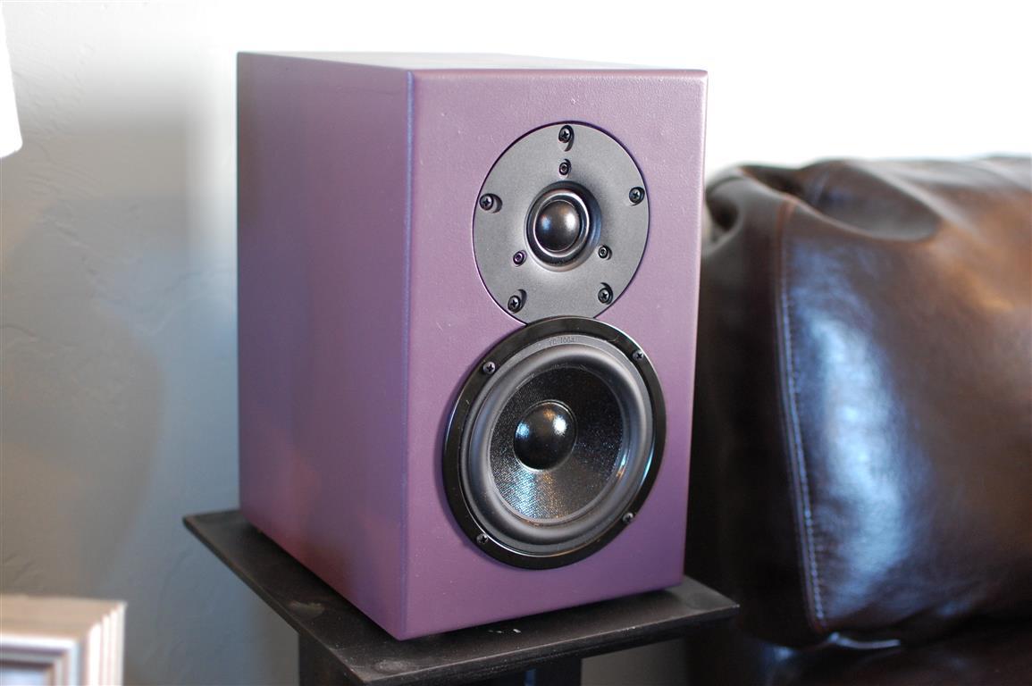
And so I present the “Mini J” two-way bookshelf speaker system. This speaker starts with a Dayton Audio Designer Series 5″ woofer and a 1″ Vifa soft dome tweeter. The DS series woofers from PE represent an excellent value, have a great look, and surprising bass response for a driver this small. Decent Xmax and a low fs make this little driver perform very well in a small cabinet size. The great upper frequency extension make crossing over to almost any tweeter a walk in the park. And for the tweeter I picked the Vifa DX25TG59-04 which has great power handling, low fs, and a smooth, flat response out to 20 kHz. It’s got a wide-roll surround around the dome and just has a great overall look to it. Besides, I’m a big fan of Vifa drivers and have been using them for many years.
 After picking the drivers I started with the cabinet design. I drew up some initial plans and started tweaking the cabinet volume and shape until I came up with something I really liked. I used Unibox to model the speaker response and ended up going with the Standard Design model which yields an f3 of 59 Hz in a 5.4L cabinet tuned to 56 Hz with no hump or dip in the response. This requires an enclosure size of 11.25x7x9 (HxWxD) using a mixed panel thickness of 1/4″, 1/2″ and 3/4″ MDF. Parts Express had also recommended a similar enclosure volume but they also recommended specific dimensions that meet what’s called the Golden Ratio. So I gave it a shot and I intentionally made the height and width conform to this Golden Ratio which is 1.618:1. There’s some great reading about the Golden Ratio over on Wikipedia if you’re interesting in killing a few more minutes. Aesthetically the most pleasing rectangular shape to look at and quite possibly exhibits superior sonic properties than other ratios. Hey, but I won’y get into that here. They look great to me and they sound fantastic too, but now I’m getting ahead of myself.
With the cabinet design complete, I moved onto the crossover design. I love the Designer Series drivers from PE because they provide FR and ZMA data for easy import into crossover designing tools such as Passive Crossover Designer. While the Vifa tweeter did not have raw data, I still made good use of SPL Trace to create data from the datasheet by tracing the FR and ZMA plots into data I can actually use. I don’t know why ALL driver manufacturers don’t provide this type of data. A picture of a plot in a .pdf file is hardly enough for doing any kind of real crossover design. You could argue that the manufacturer raw data isn’t exactly ideal either, but it’s a start.
 I’ll try and be brief on the crossover design and my methods of doing crossover design because quite frankly it’s just that, my method, and I’m still tweaking and proving my method with each new speaker design. I’m not sure I’m there yet, but this is actually a big part of the fun of speaker building. I always shoot for the simplest crossover with the fewest elements to achieve the flattest FR and a decent impedance. I typically add a Zobel network to the woofer to flatten the impedance above fs which helps with the high-frequency roll-off. The woofer is a 12dB/octave set at about 2,700 Hz with a cap value that is about double the textbook design value. This provides a sharper roll-off without peaking just before cutoff. The tweeter also ended up being a 12 dB/octave but wired in phase with the woofer. The inductor in this case is also slightly tweaked to be lower than the textbook value which also increases the slope slightly and according to the simulation blends/sums well with the woofer on-axis. I also added a 4 ohm series resistor and a 20 ohm shunt resistor (aka L-pad) to pad the tweeter and match the overall level of the woofer. It also brings my impedance of the system up to around 8 ohms which is where I wanted it for an easy load to even the cheapest amps.
 Now that I had some crossover values assigned I started putting parts in my cart at Parts Express. Another fun part about building speakers, getting to buy everything. Since the crossover design at this point was just a model, I do like to buy multiple different values of capacitors and resistors so I can tweak things in a listening environment. I didn’t buy a bunch of different value inductors because they are quite expensive and I just hoped that my simulation was close enough to allow me to only tweak the caps once I got closer to being done. Caps are cheap, especially electrolytics, so I bought every value from 3.3uF all the way up to 15 uF which would allow me several tuning options on both the woofer and the tweeter and the zobel network. I also bought several values of resistors so I could adjust the tweeter level as needed. One day I would like to have every standard value inductor/cap/resistor just so I can have the ultimate freedom to tweak but that project will have to wait for another day.
I was just about ready to cut wood at this point, so I drew up a cut sheet and got started. The cutsheet in this case is a little unique. The box design consists of (3) panels of 3/4″ MDF that make up the front, brace and back each piece being 6″x10.25″. The sides and top and made up of 1/2″ MDF which are cut at 8.75″x10.25″ (sides) and 8.75″x7″ (top/bottom). These cuts were a breeze on my table saw and were designed this way so as to allow the table saw to be set to each dimension only once and every cut made so that every cut that is dependent on a flush fit when assembled is exactly the same size, even if the saw isn’t cutting each piece at exactly the width it should. It doesn’t matter because all the pieces that fit together that require that dimension just end up being the same. The only cut that matters is the width of the top and bottom pieces which need to be cut to whatever the width of the front/brace/back ended up being +1.0″. With a table saw, every cut comes out near perfect anyway but even if they didn’t, this design allows for a little slop in each cut while still providing a perfectly flush fit.
Anyway, I cut the wood, built the boxes, sanded the boxes, painted the boxes, built the crossovers, tweaked the crossovers, measured the responses, installed the drivers, added some polyfill the port and the terminal cup and alas I was finally done. And just in time for my daughter’s birthday the next day. I was able to whip these out in only 4 days mainly just working a few hours each night after the kids had gone to bed. So they are a super easy project but were a lot of fun to design and build and they sound absolutely fantastic. I like the fact that I could tailor the sound a little knowing what type of music will be played on these speakers. While they don’t have a lot of low-end presence, they make up for it with a smooth, solid-sounding midrange and treble. I’m not all about that bass (no treble) and can appreciate a speaker’s ability to produce vocals without coloration. The boxes are rock solid too, very little resonances despite the 1/2″ MDF. But enough fluff, here’s the meat and potatoes. Click here for a parts list from Parts Express. Check out some of the build pics below as well as pics of the final product. Hope you enjoy!
Finally, scroll past the pictures for in-room measurements and near-field plots of various crossover options and L-pad values I had considered. In the end, I chose what “sounded best” to me regardless of what the plots actually looked like.
-

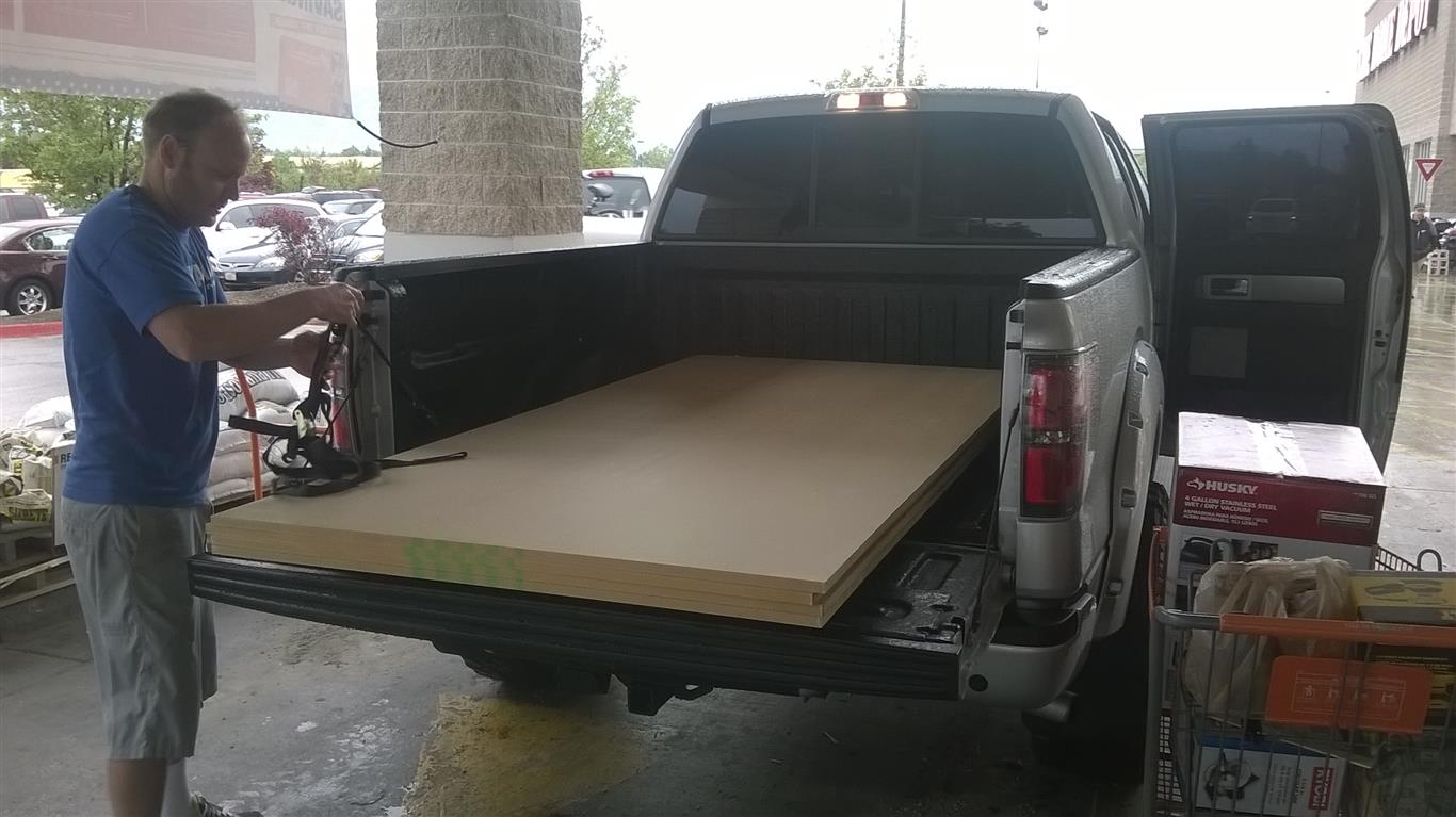
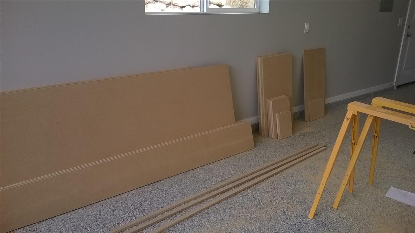
- 1/4″, 1/2″ and 3/4″ 2’x4′ MDF

-

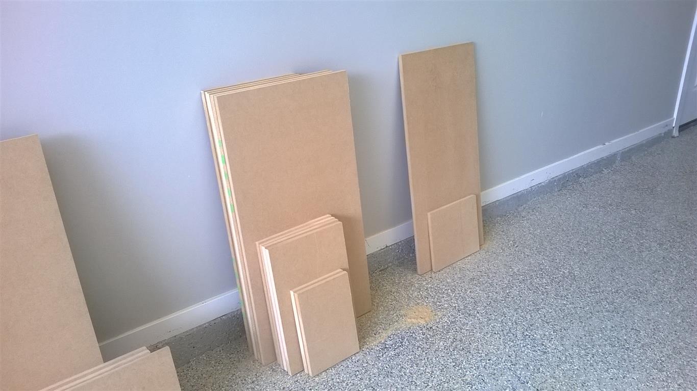
- Sides cut to 8.75×10.25″

-

- Tops cut to 7×8.75″

-

- Front, brace and back cut to 6×10.25″

-

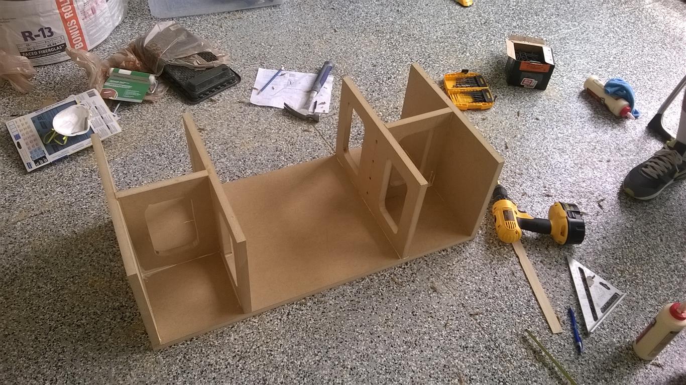
- Window bracing

-

- Window bracing cut

-

- 1/4″ roundover on window brancing

-

- Front, brace and back attached to side 1

-

- (9) 1-1/4″ drywall screws hold on each side

-

- Interior shot

-

- Titebond Glue is awesome stuff

-

- Front, brace and back attached to side 2

-

- Two speakers with sides, front and back complete

-

- Holes cut for woofer and tweeter

-

- Holes cut for port and terminal cup

-

- Fit check. They fit.

-

- Tops and bottoms attached

-

- 1/4″ MDF being marked for flush-mounting of tweeter

-

- About 4.10″ should work

-

- 1/4″ MDF on front allows tweeter to be flush-mounted

-

- 1/4″ MDF glued to fronts allow tweeter to sit flush

-

- 1/4″ roundover on the four sides front

-

- Back

-

- One more fit check

-

- First time listening

-

- Protoboard used to test various crossover options

-

- EMC8000 Mic and REW used to measure responses of drivers

-

- Prepping for finish with putty and sanding

-

- Crossovers mounted to 1/4″ MDF

-

- 16 AWG wire and point-to-point wiring on crossover board

-

- Crossovers complete!

-

- Painted w/Behr Premium Paint and Primer-in-One the color my daughter picked out

-

- This is a satin finish with some sheen but not too much

-

- I can’t remember the name of the color – but it’s dark purple

-

- Drivers and crossover about to be installed

-

- Crossover fit-check. Polyfil added at this point though I didn’t take any pictures

-

- First shot final of the Mini J
-

- A few more pics

-

- Just trying to get some different angles

-

- I put them on my old speaker stands

-

- Nice close-up


-

- The read of the box shows the terminal cup and port

-

- A couple shots of the speakers together

-

- Another shot

-

- Back shot

-

- They need some stands of their own


-

- Front shot on stands of the Mini J Two-way Bookshelf speakers

-

- Taking some final measurements with REW

-

- I had to see how they compared to some of my other speakers so here’s the trio compared

So with most speaker projects just getting that first listen is an awesome feeling. These speakers definitely sound great. Good balance between the woofer and the tweeter and they have a really good soundstage, so music doesn’t sound like it’s just coming straight out of these two drivers. You close your eyes and listen and you can’t really tell where the speakers are located. The music just fills the room in front and behind. And I love that. No harshness out of the tweeter either. You can put your ear right up to it and it sounds clean and smooth. So here’s some FR plots. I don’t try and read too much into every little bump and valley, I’m mainly looking for an overall balanced sound. The slight dip near the crossover freq is mainly due to the close proximity of the microphone in between the drivers which actually shows up in the PCD model as you move the listening position closer to the speaker. I suppose if I had a little more time and a few extra cap/inductor values on-hand I may have tried achieving a slightly flatter response, as I am sure it is achievable, but for now I’m going to call it good enough and overall I am happy with the results.
-

- First measurements of the 5″ DS driver in free-air

-

- Tweaking the crossover and taking measurements

-

- Woofer + Tweeter Response

-

- A few more measurements

-

- Tuning frequency measurement

-

- Comparison with two other bookshelf speakers

-

- Near-field vs. far-field

-

- Final frequency response plot

The last thing I did was take my measurement gear outside and ran some FR plots in basically a near-anechoic environment. I took a bunch of measurements at several different distances with both the tweeter wired in-phase and wired out of phase (meaning + to + and – to – on both woofer and tweeter) therefore actually making the speakers acoustically out of phase due to the 12 dB/crossover yet quite possibly back in phase due to the delta in physical relationship between the acoustic centers of the woofer and the tweeter. Confused yet? These plots at least tell me that everything is summing properly on-axis which yields the flattest FR. Notice that these speakers do not have baffle step compensation as is evidenced in the plots below. I decided not to incorporate it since these speakers will almost always be backed against a wall in a very small space, I didn’t want the bass and lower-midrange region to be too aggressive. You can see from all the measurements, in-room included, that there is a definite rise in amplitude between 500-700 Hz. John Murphy of True Audio came up with a quick formula for approximating the -3 dB point given the baffle diameter (or width) which is f3 = 380/W where W is the width of the baffle in feet. These speakers are 7″ wide, or 0.588 feet which amounts to a -3 dB frequency equal to 655 Hz. That matches well with the measured data shown here. Even without BSC, the speakers sound fantastic in-room, but if I were to implement it, I wouldn’t do more than 3 dB and I would shoot for a corner of about 655 Hz.
2021 Update: So I’ve recently got back into measuring and tweaking some of my speakers and this was one pair that I always wanted to improve. Looking back at the response plots it’s pretty obvious that the crossover design fell just short of providing an nice, even, flat response. It looks like baffle losses and maybe a bad summing at the crossover point result in this kind of bumpy, uneven response. I think at the time I was just pushing to finish these before my daughter’s birthday the next day I called it good enough. This weekend I spent a little more time and with a handful of additional crossover parts on-hand, I made some minor adjustments that really make this speaker shine now. If you built this speaker based on the original design then I present an updated crossover which provides about 3 dB of baffle step compensation, moves the crossover point of the woofer and tweeter down a bit and lowers the overall output of the tweeter to balance it with the new baffle step network. The result is a much flatter response, more bass, less midrange presence and better matching with the tweeter at the crossover point.
 The new 2021 crossover can be seen here. The basic adjustments are as follows: first off I increased the series 0.8 mH inductor to 1.3 mH and the shunt cap from 8 uF to 17.7 uF. This pushes the start of the crossover, or the start of the baffle compensation circuit, to about 300 Hz, where the slope is rolling at about 6 dB/octave. By the time the response hits 2 kHz we are down 4 dB from where we were before. The larger cap helps to set a new 12 dB corner of about 1600 Hz at which point the crossover transitions to a 12 dB octave slope so we are 30 dB down by around 6.5 kHz. There’s some leftover cone break-up modes at around 4.5 kHz which you could clean up by shunting a 1 uF cap across the 1.3 mH inductor, but I believe it was not necessary as the peaking is pretty subtle. The original Zobel network was left unchanged. Overall this brings the response from about 400 Hz to 2 kHz down a bit making that region in the response much flatter than it was before.
The tweeter now needed to be attenuated a bit to match the new lower response of the woofer plus it needed to be pushed lower in frequency to fill the gap that the woofer left due to the lower crossover point. This was accomplished by increasing the series cap from 3.3 uF to 7.8 uF and increasing the 4 ohm series resistor to 8 ohms. This provides a pretty decent crossover point to the woofer and provides the flattest on-axis response shown here. I’ve given these speakers another listen and believe they sound much better than before, more neutral, more bass. If you’ve got them near a wall, the treble might sound a little flat, you can opt for a 6 ohm series resistor in the L-pad instead of the 8 and brighten it back up another dB or so. Anyway, that’s the update, check out the before and after response plots below and let me know what you think!


 I don’t know exactly when it happened or how it came about exactly, but one day my wife said to me, “I want a hall tree”. I replied, “Um, you want a tree in the hall?” She said, “No, crazy, I want one of those things, like an entryway bench, but with coat hooks so you can hang your coat and the kids can hand their backpacks.” Ah yes, I did know what she was talking about and a quick


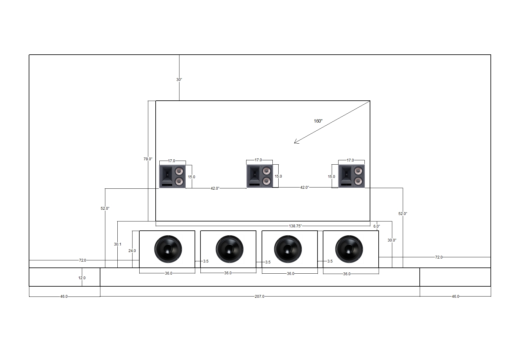
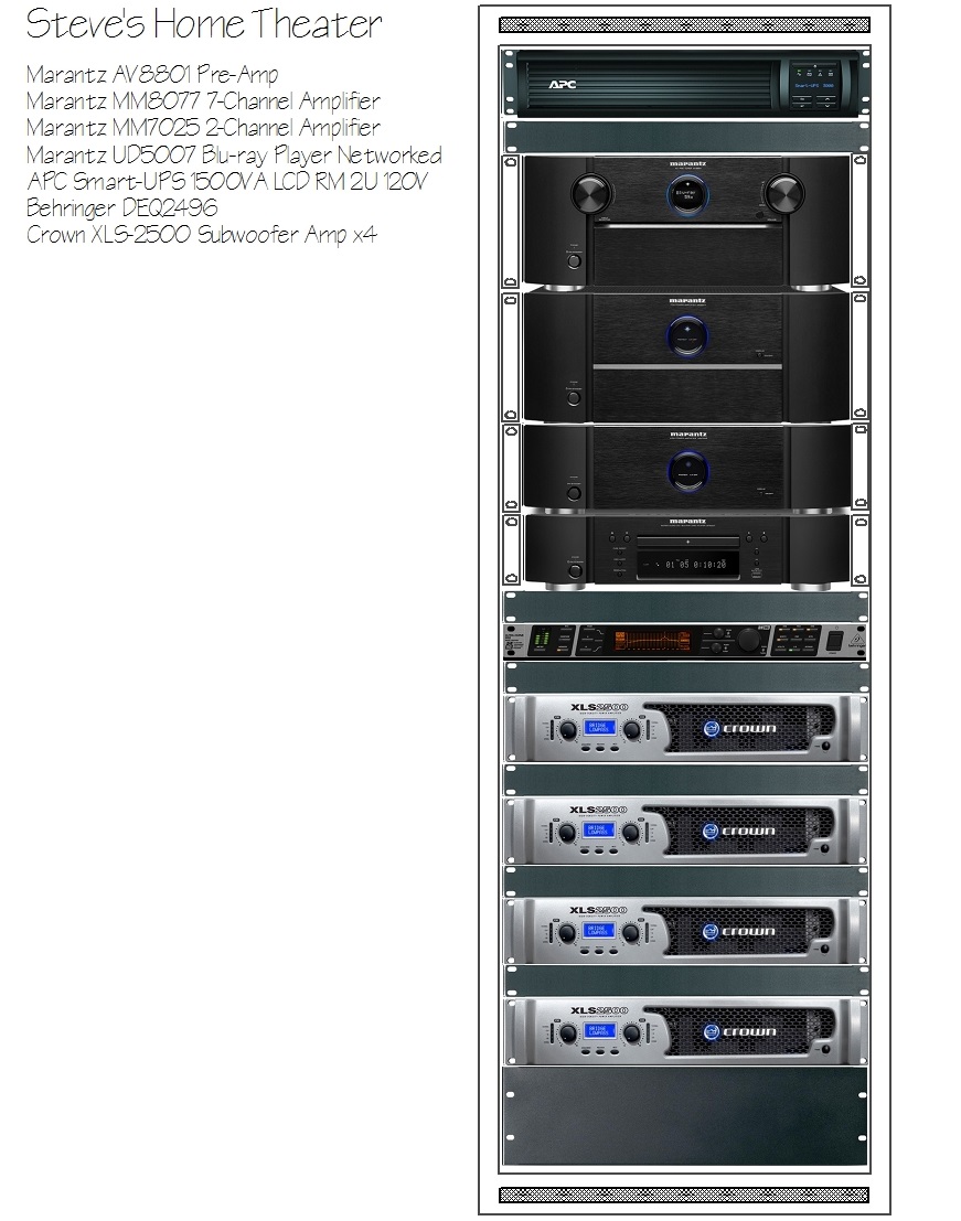
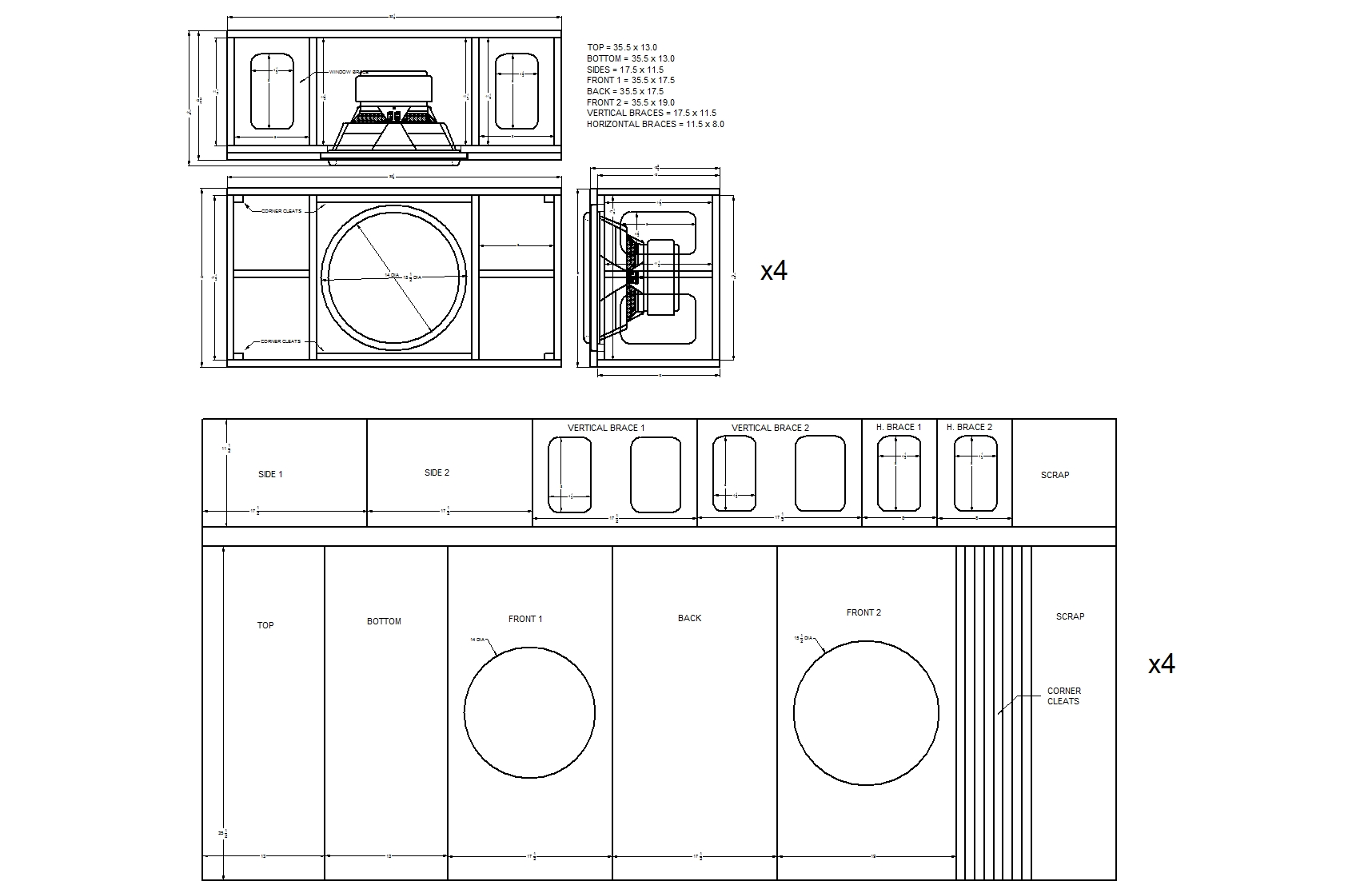
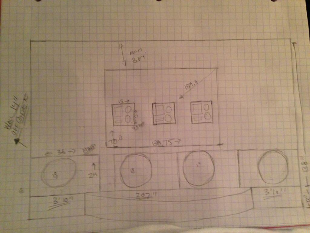
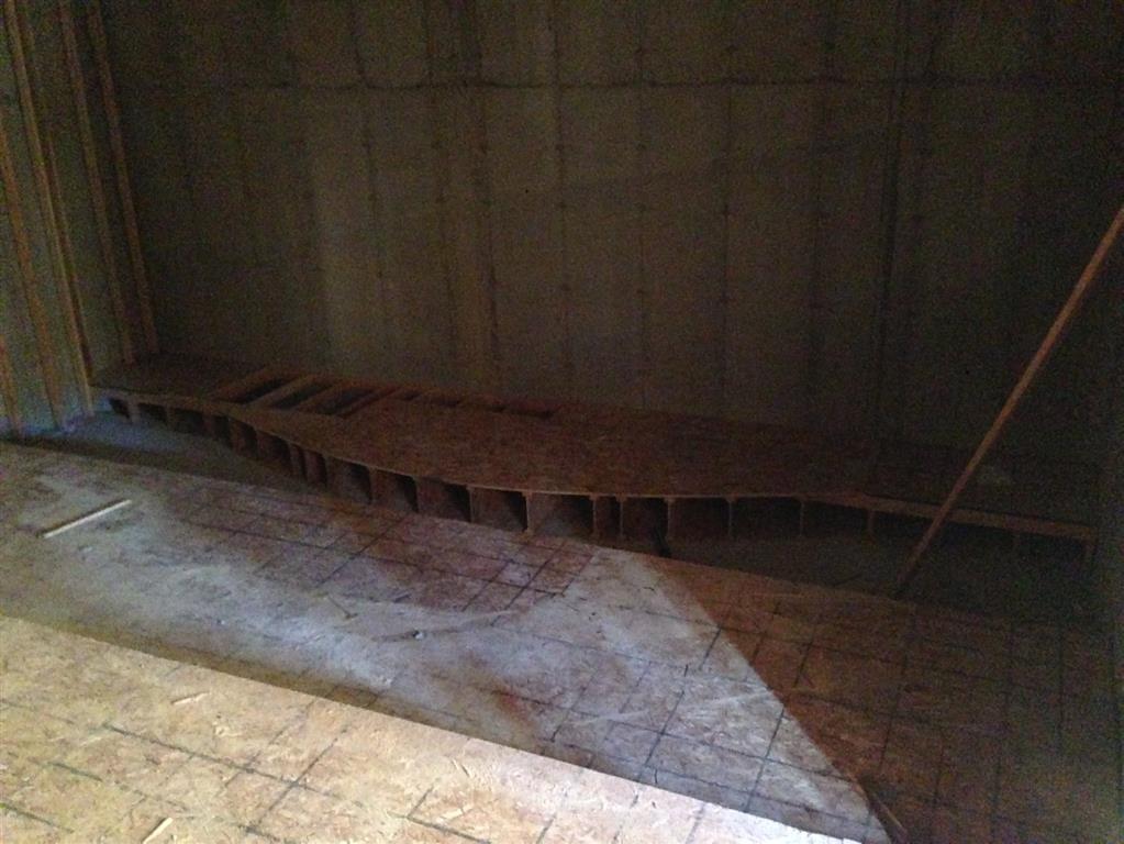
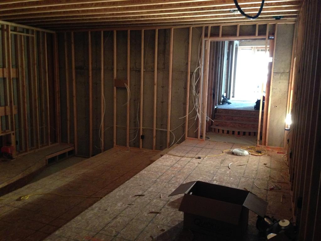
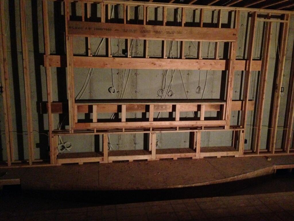
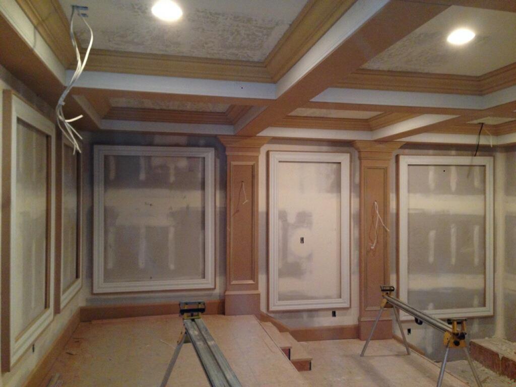
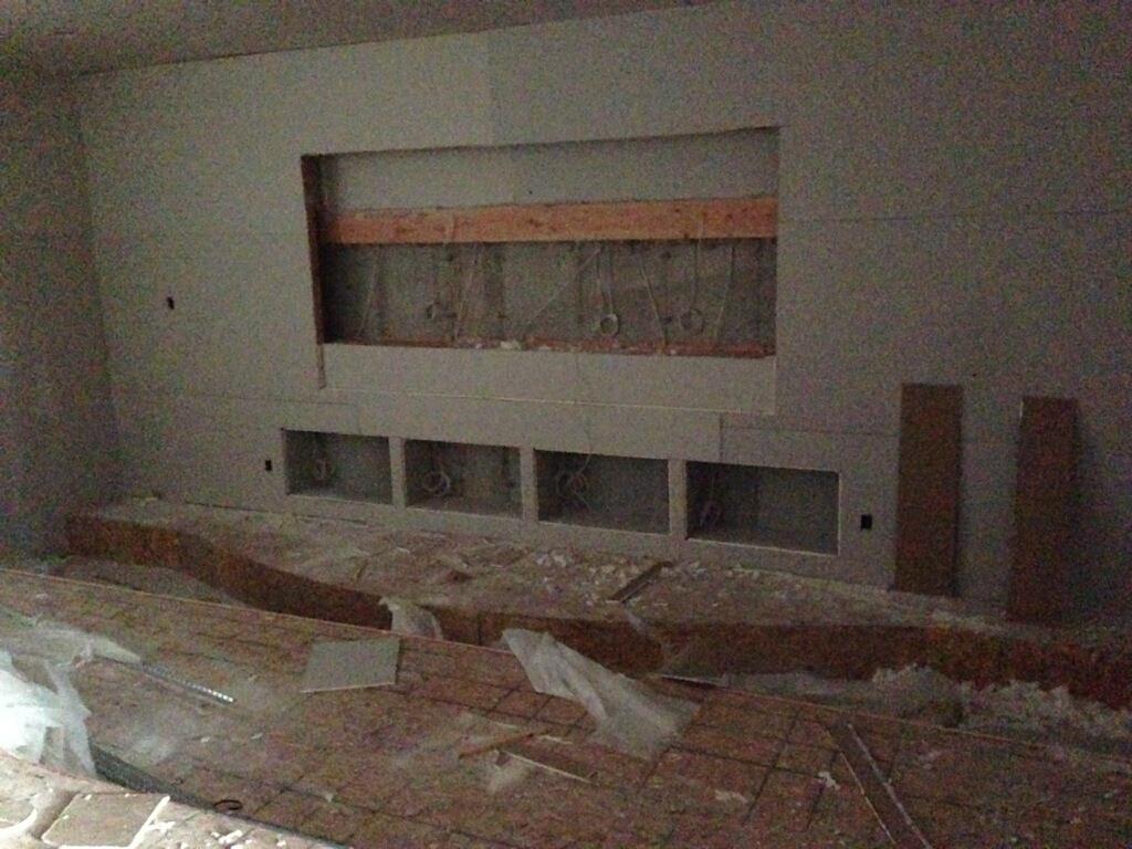
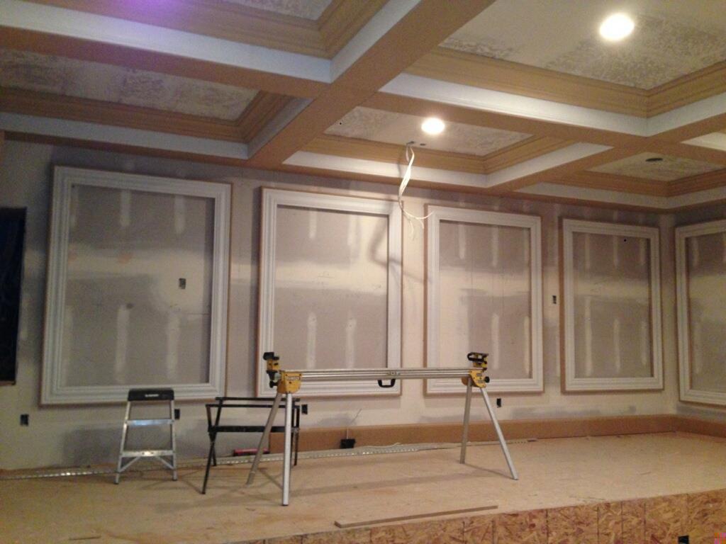
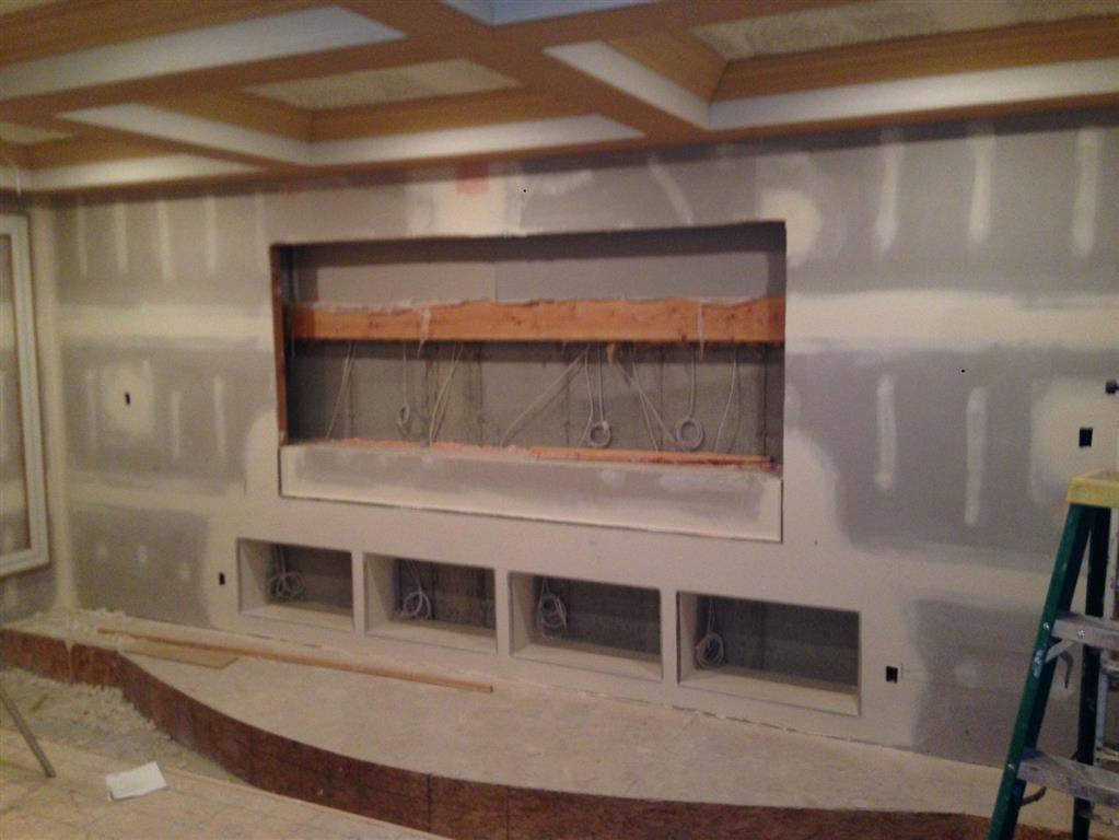
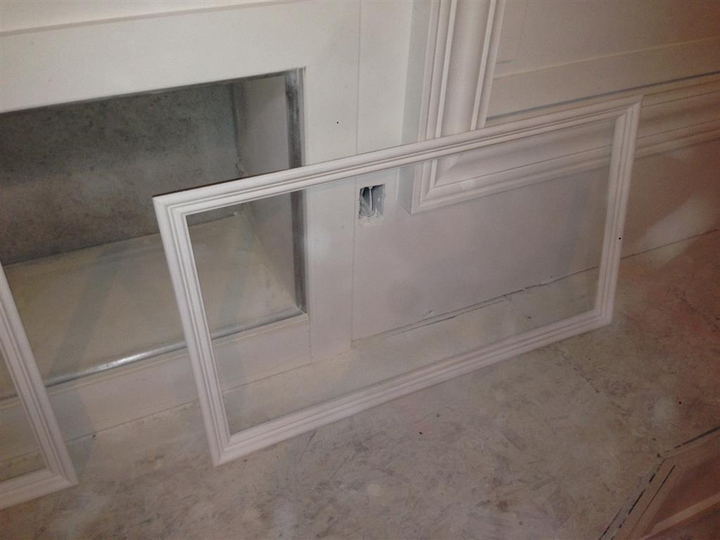
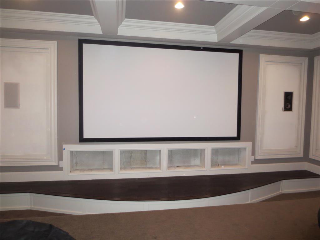
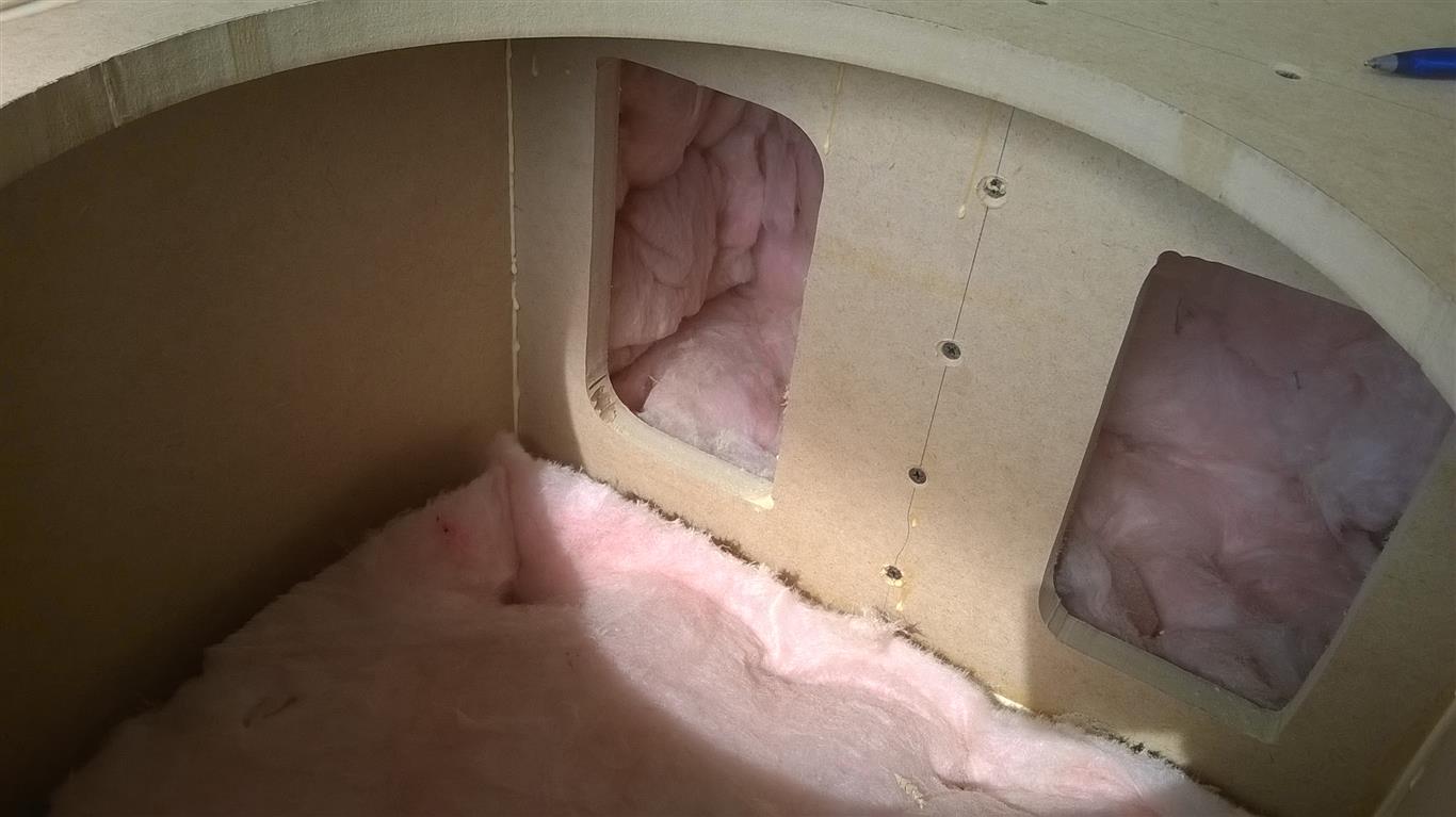
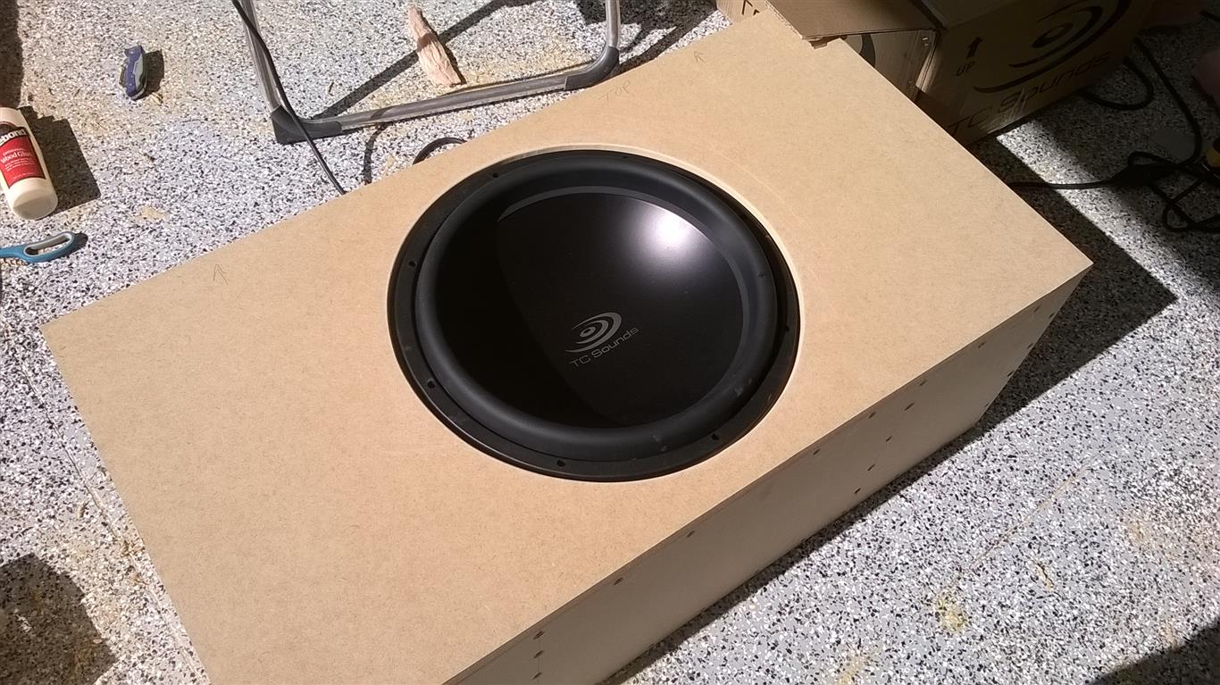
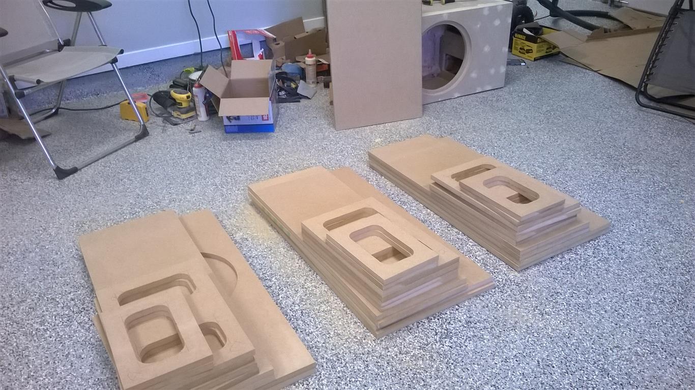
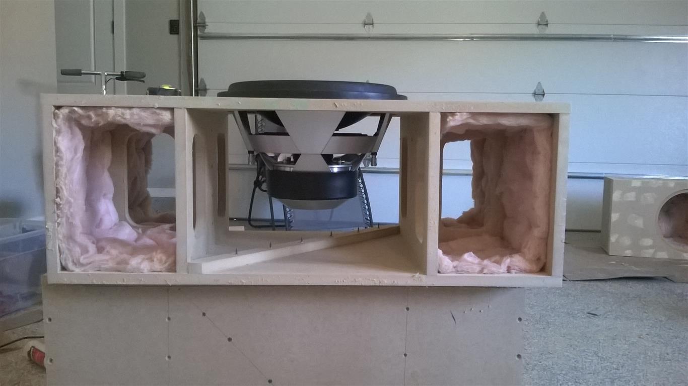
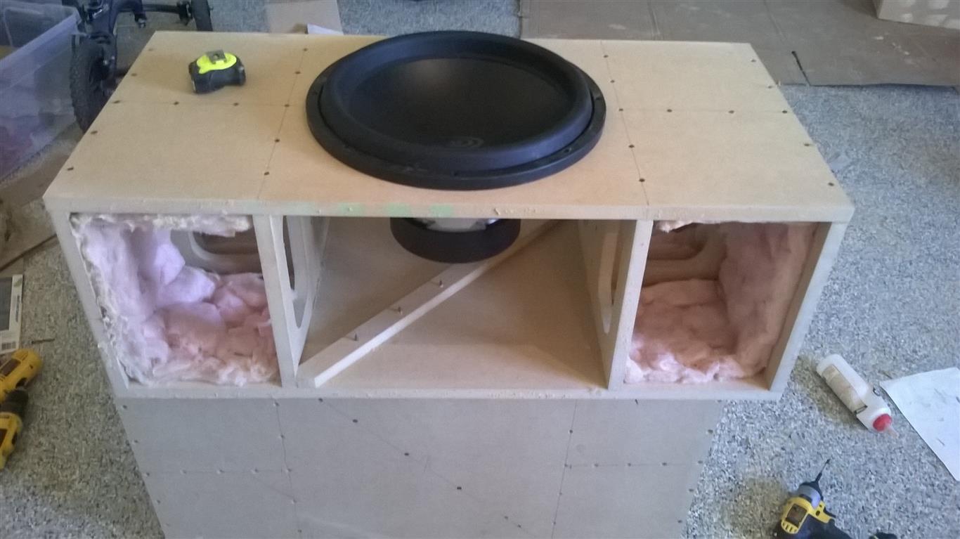
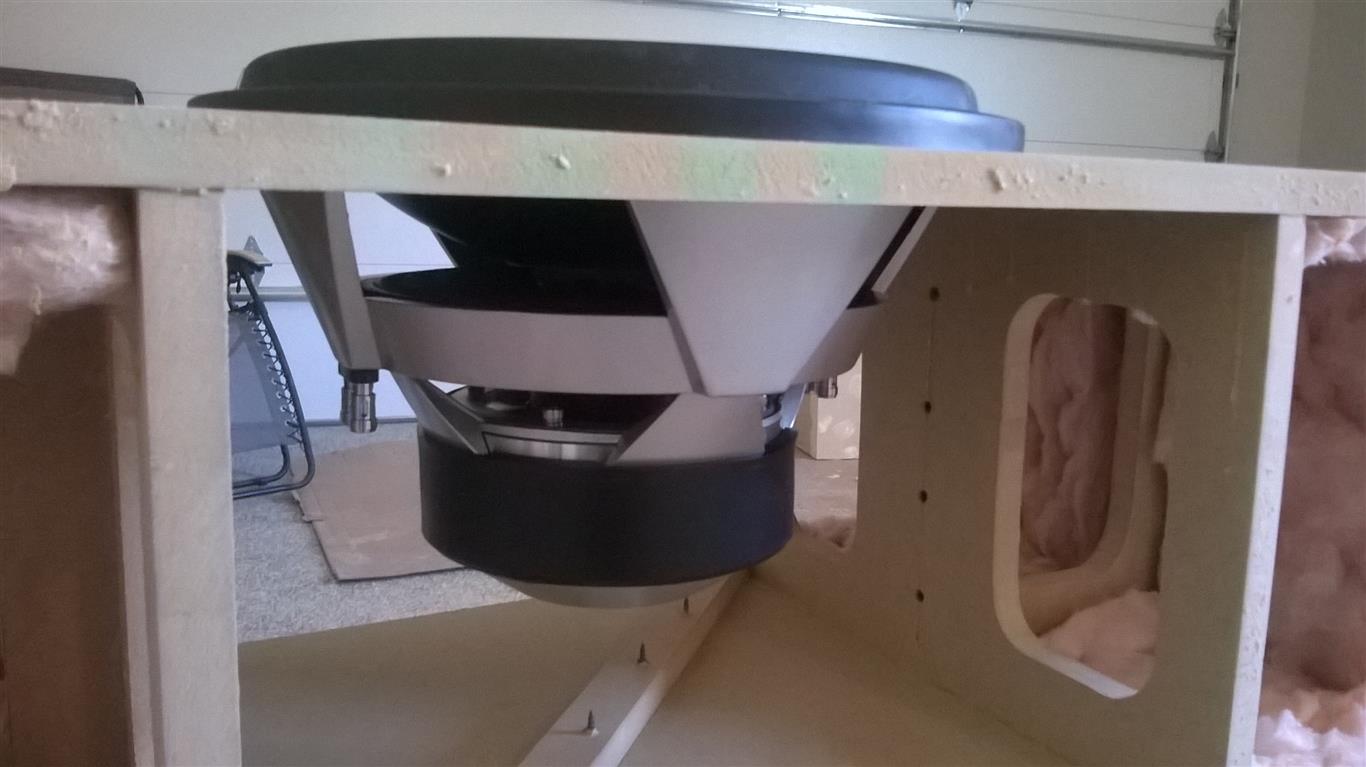
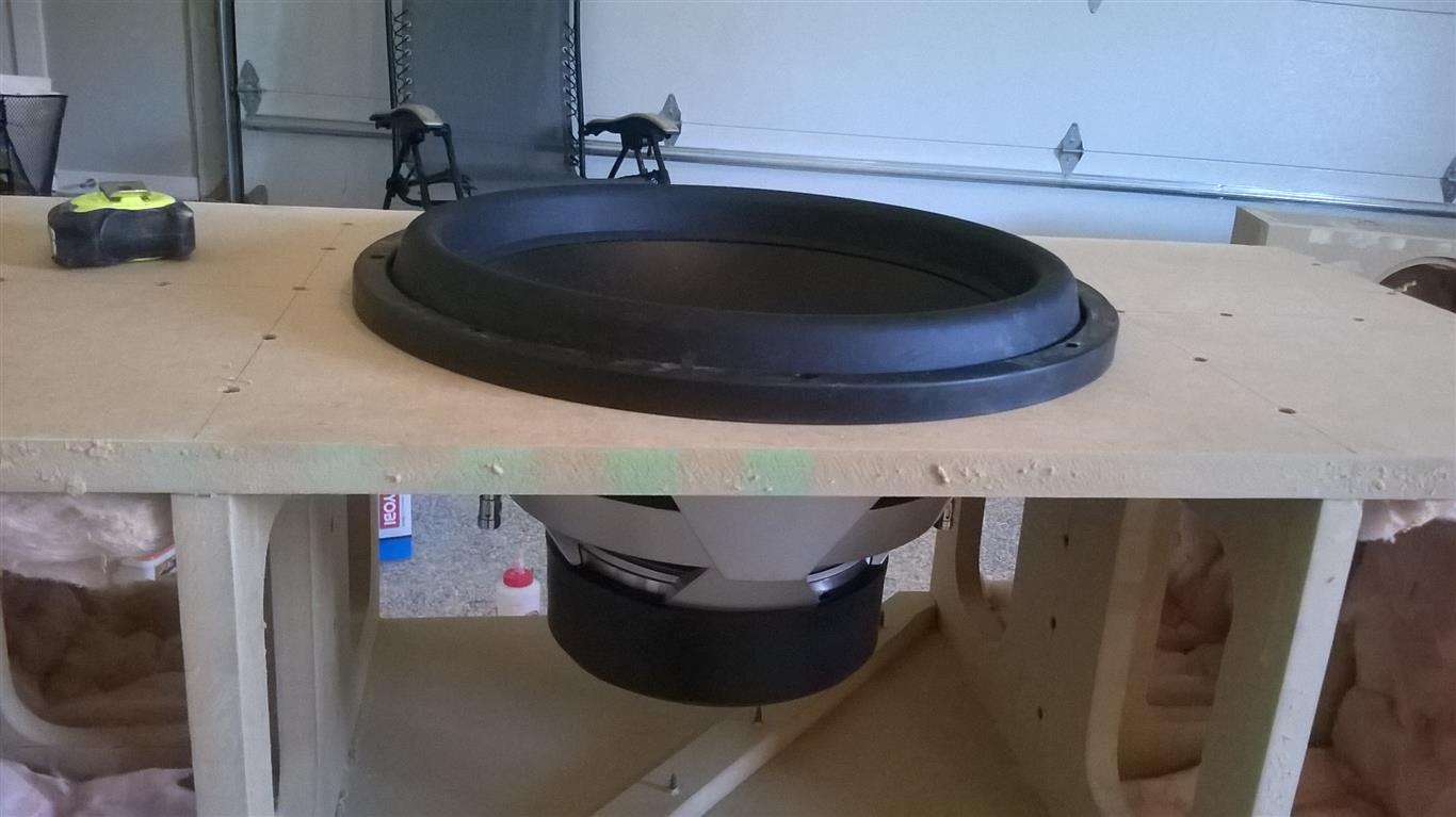
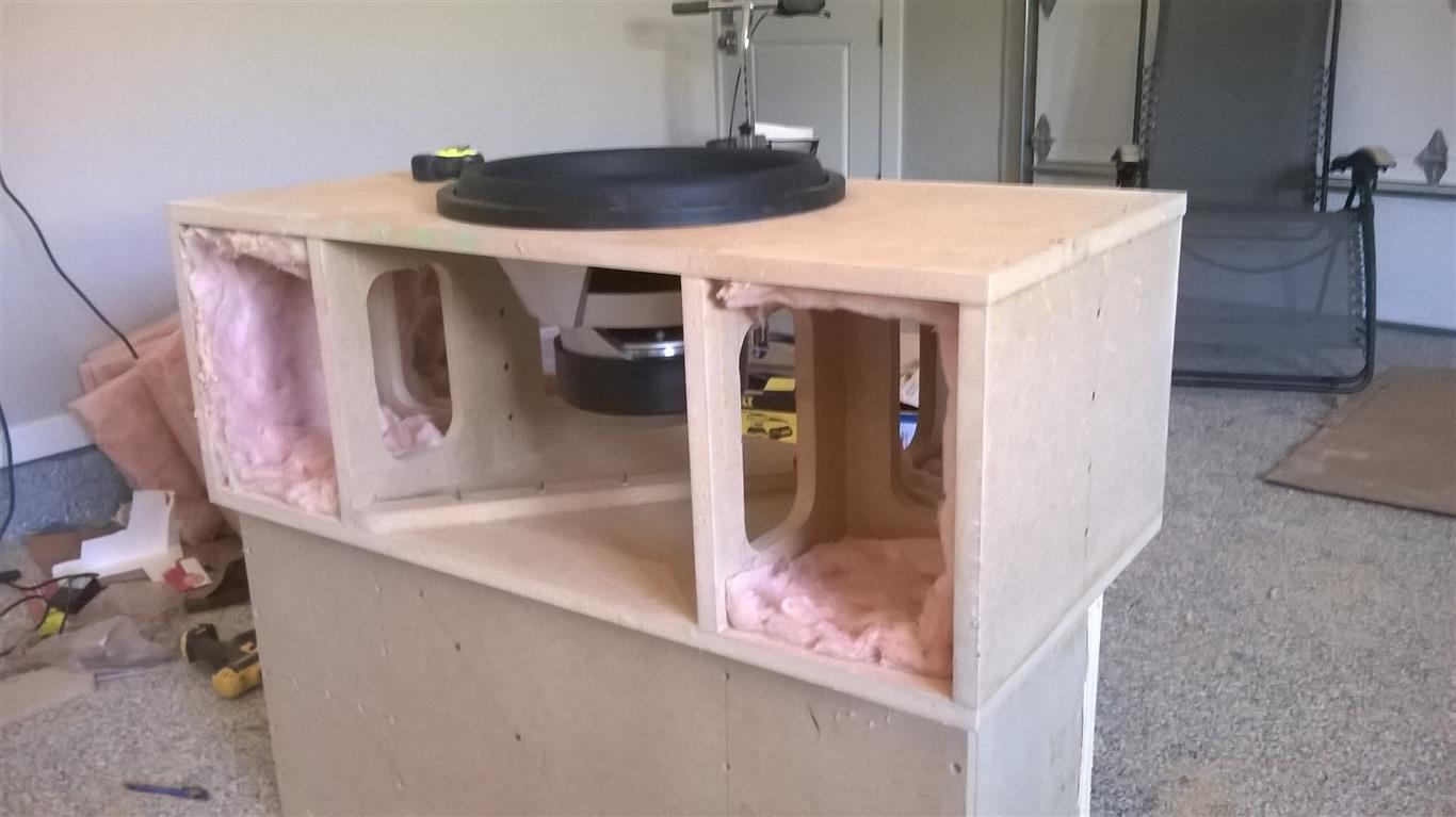
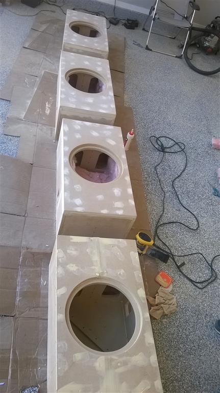
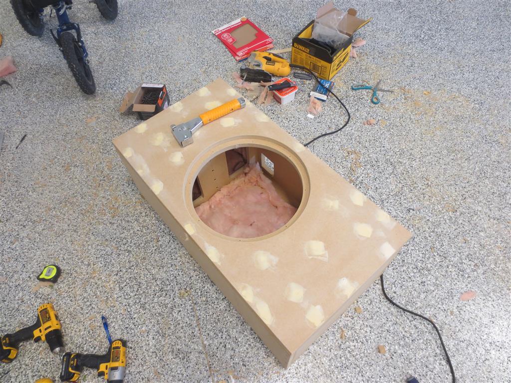
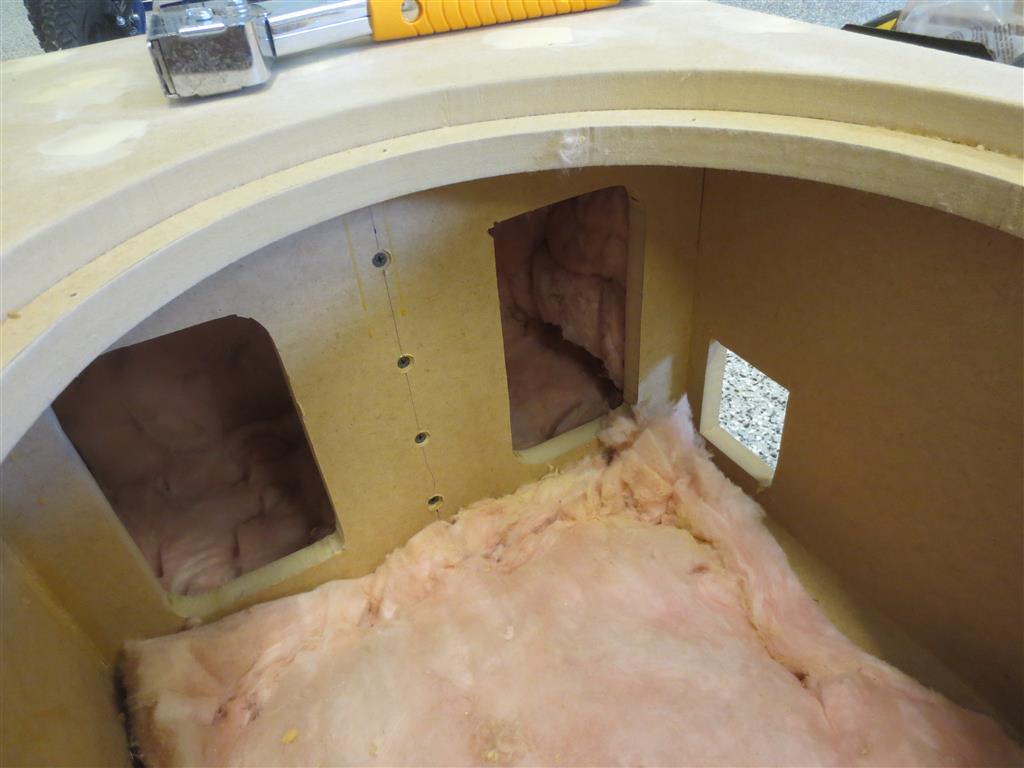
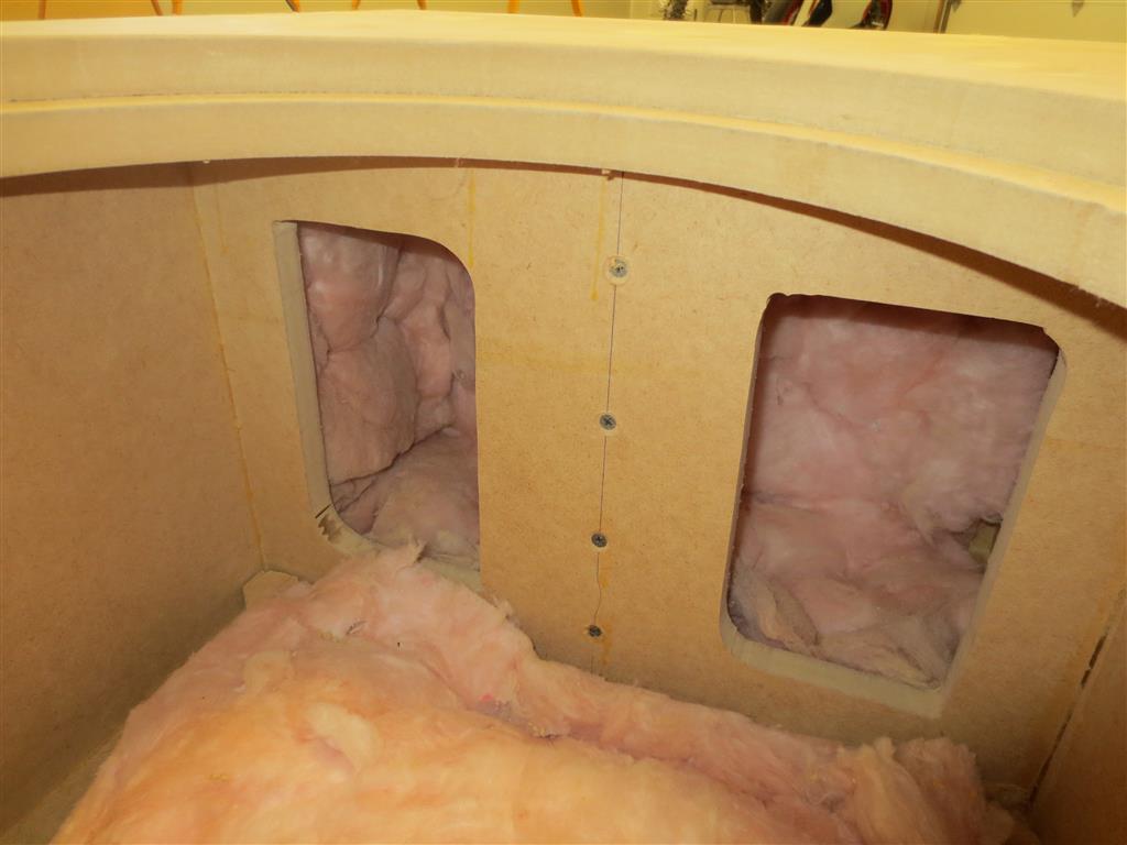
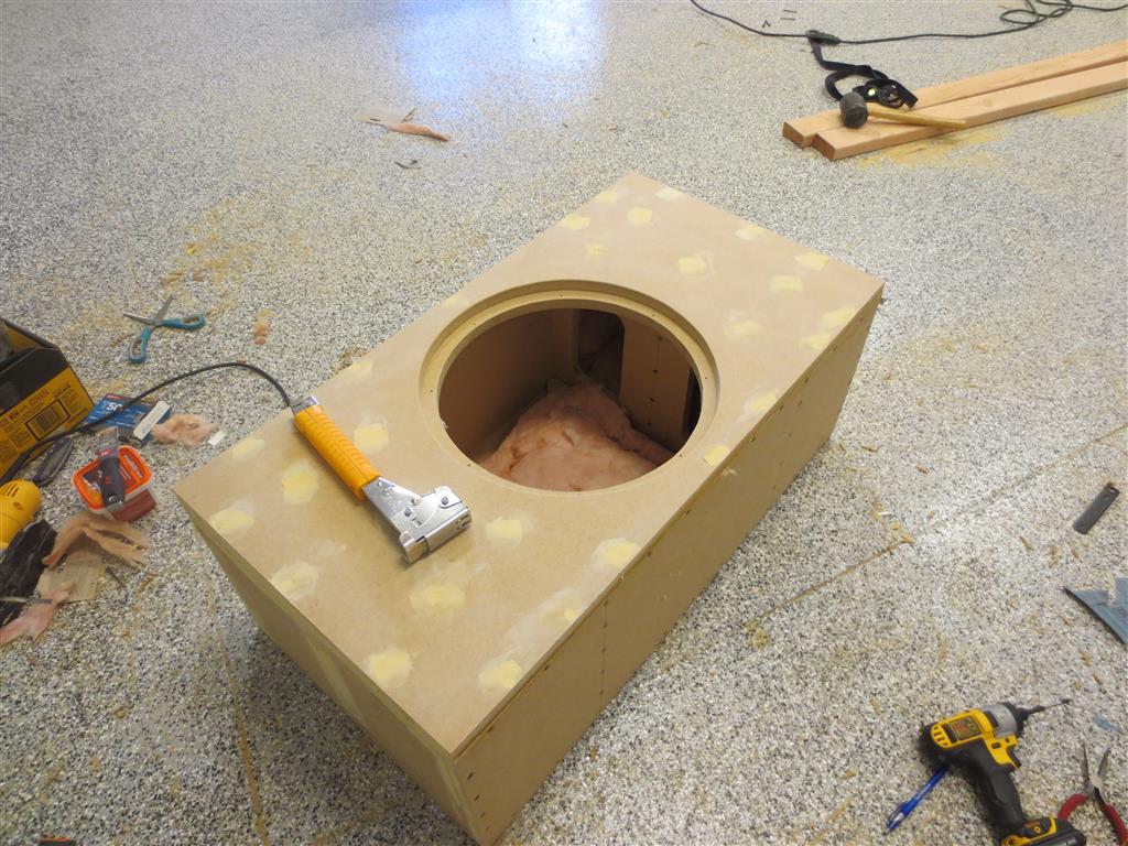
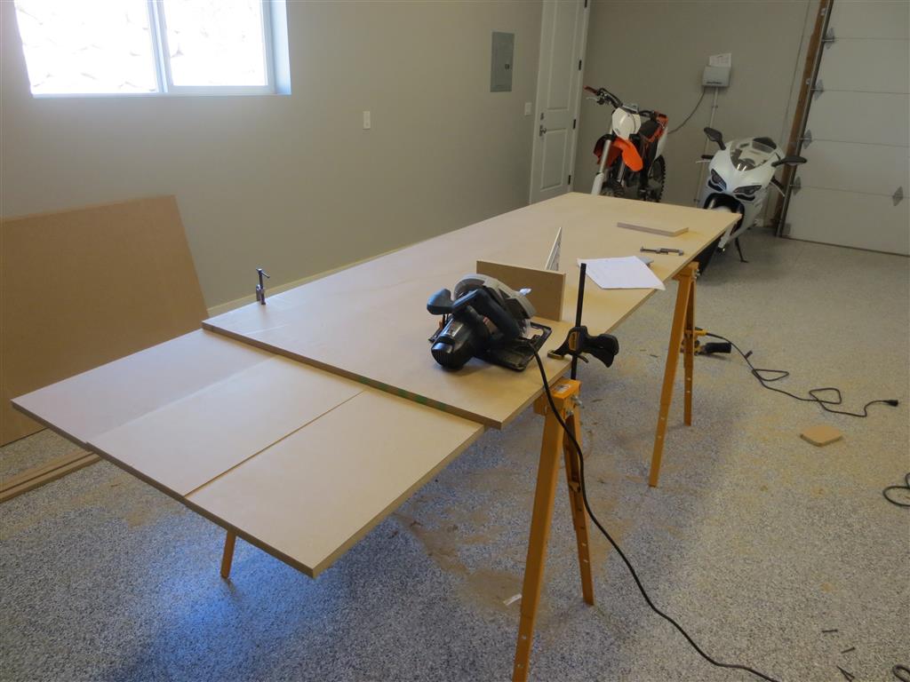
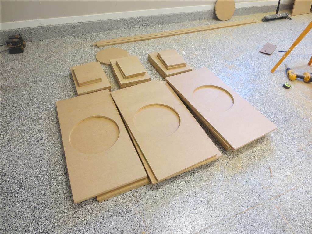
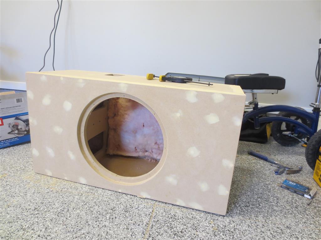
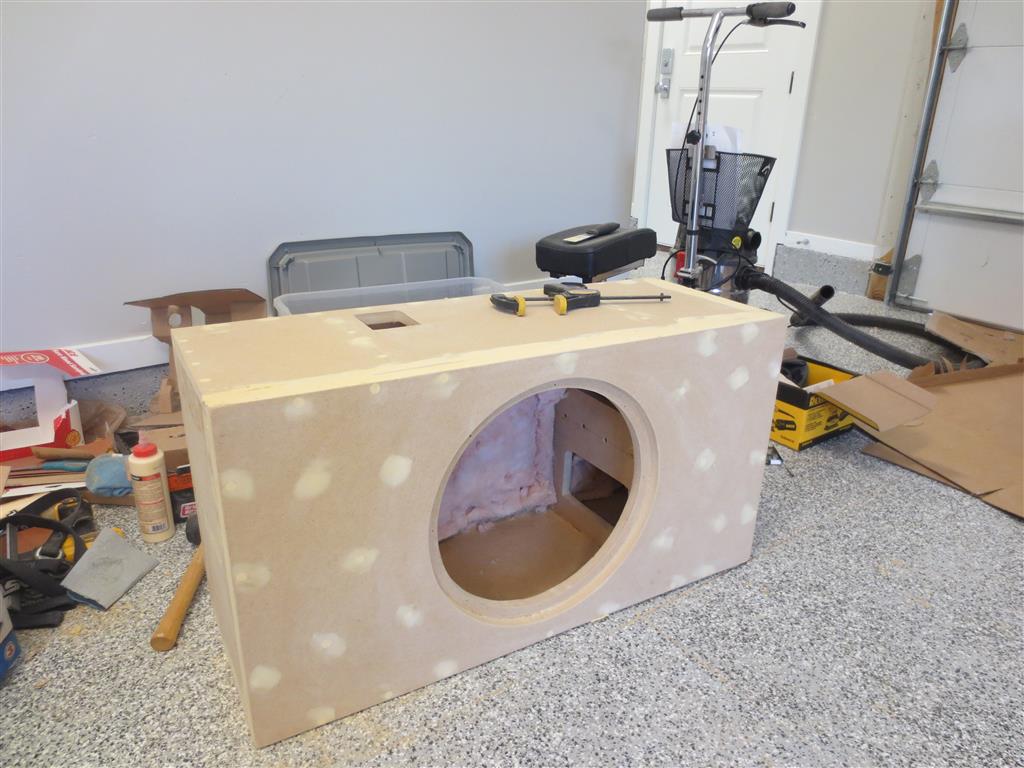
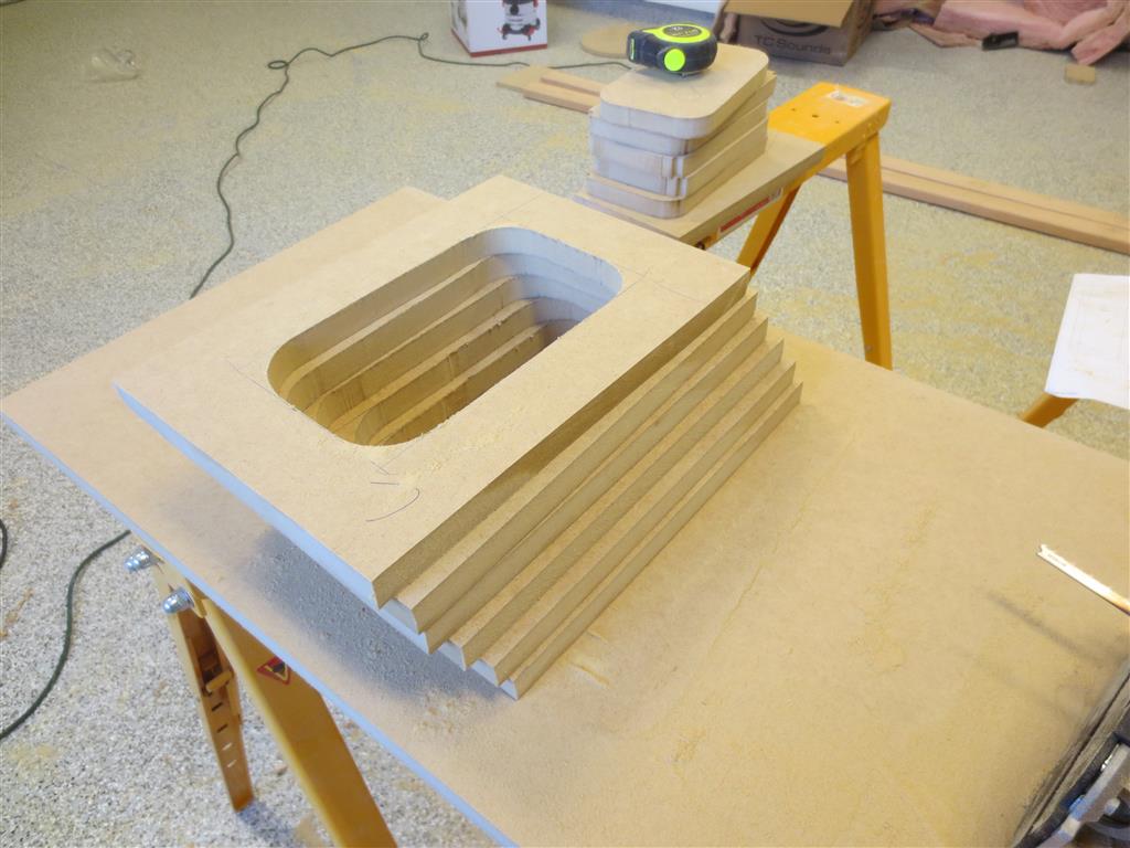
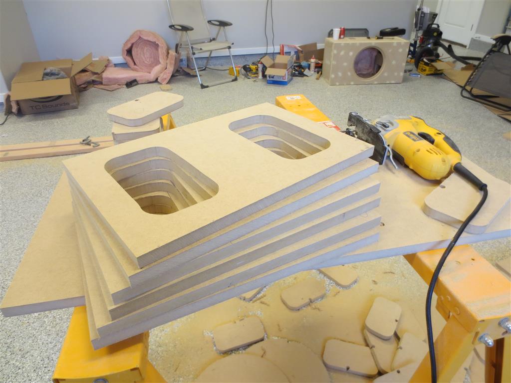
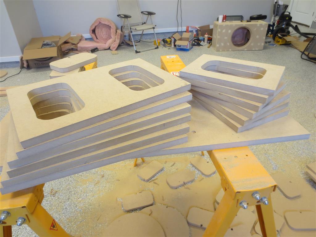
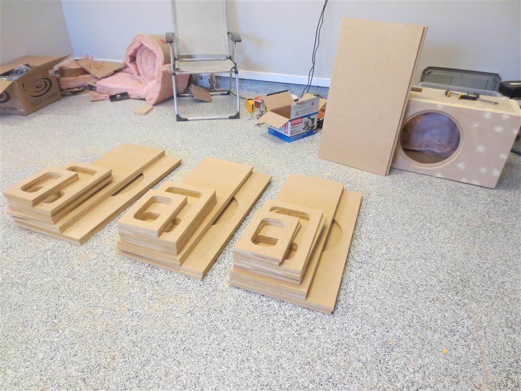
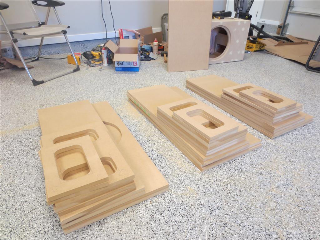
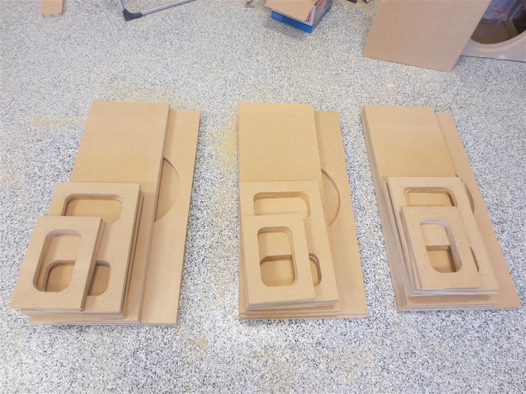
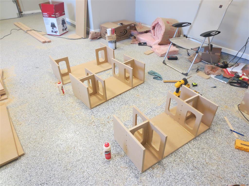
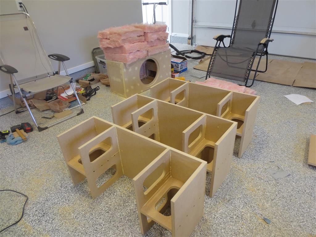
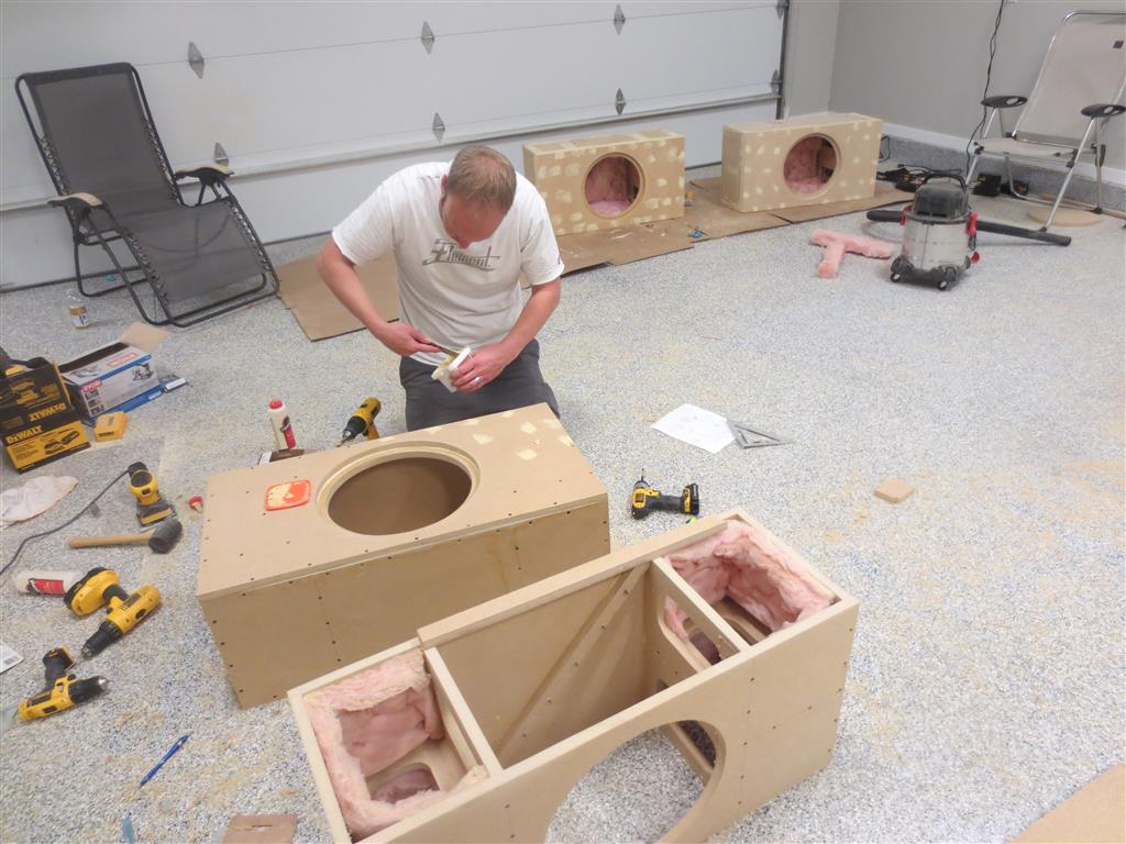
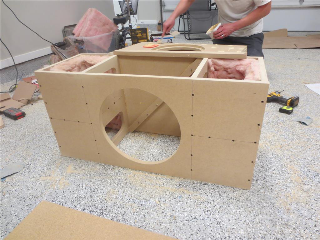
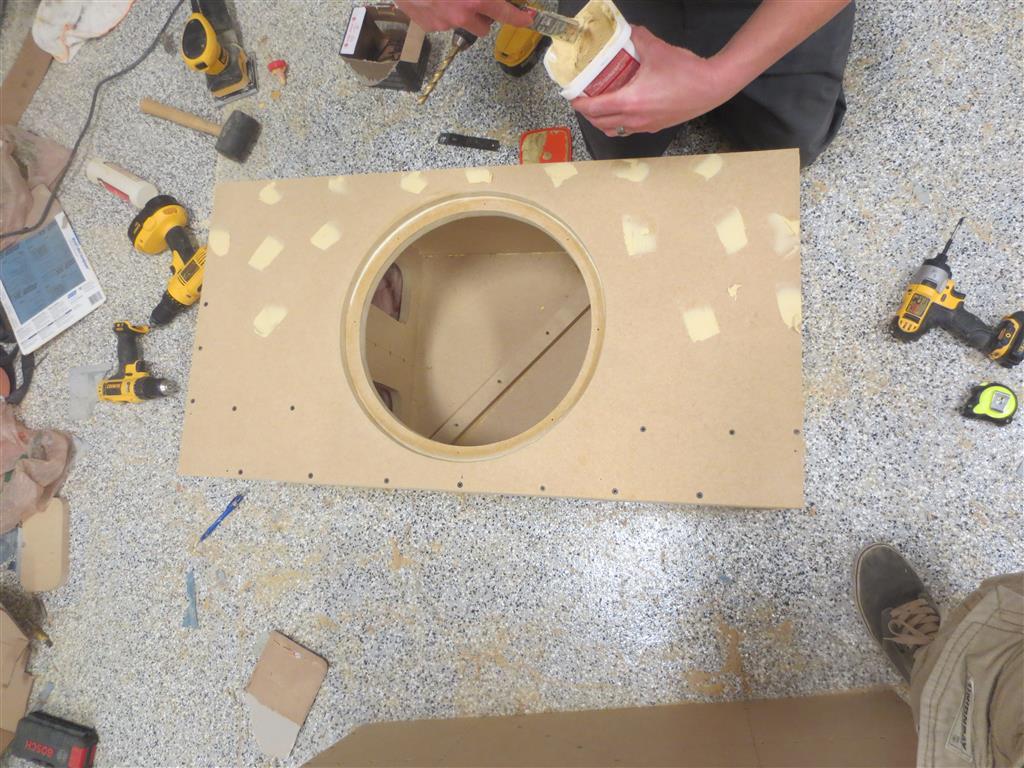
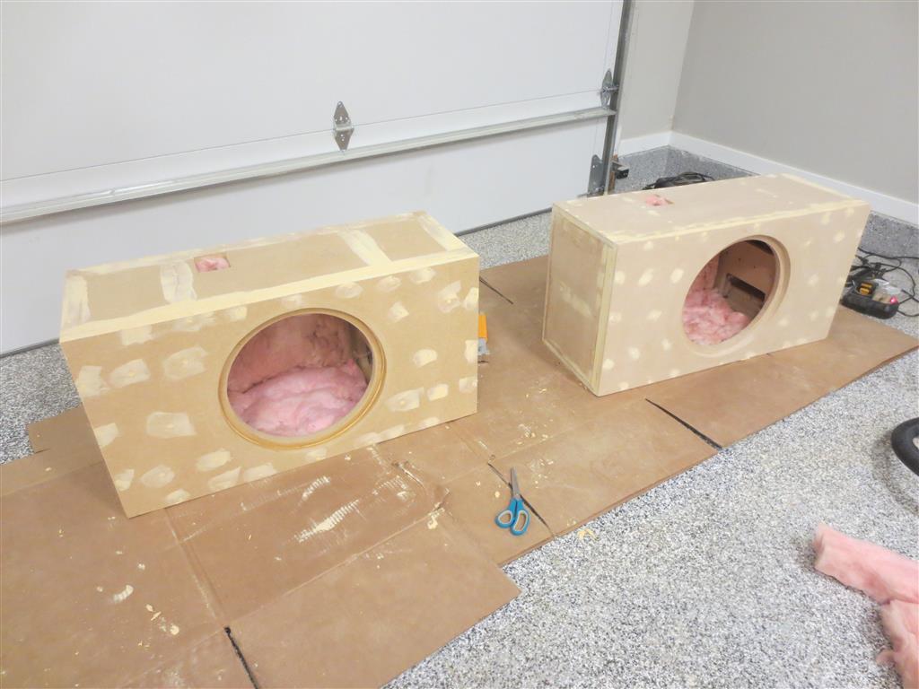
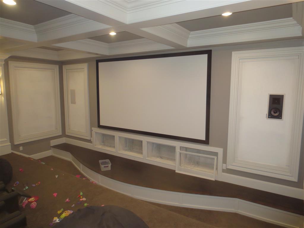
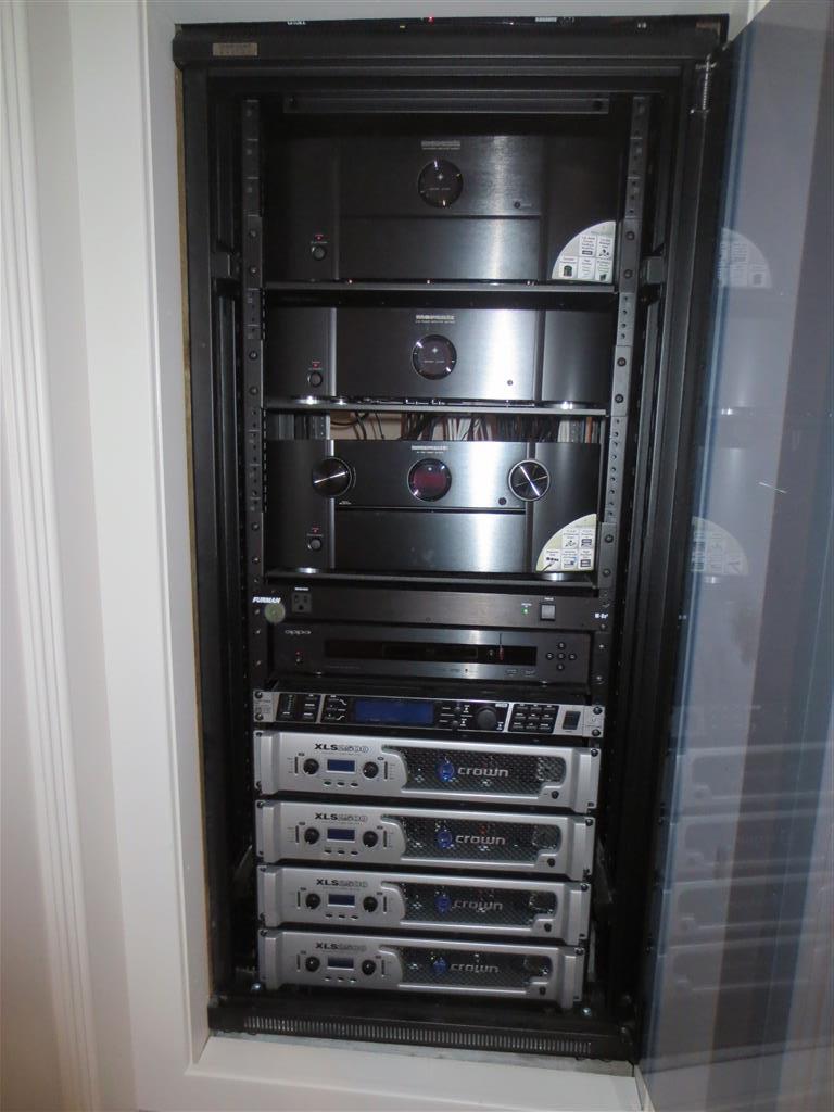
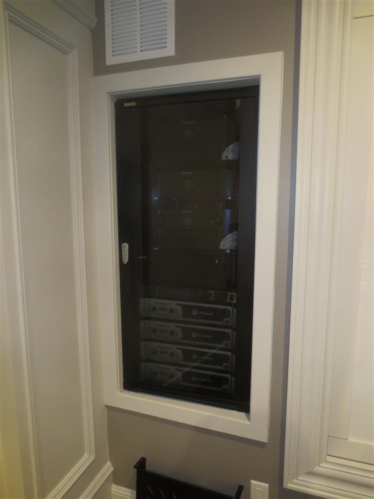
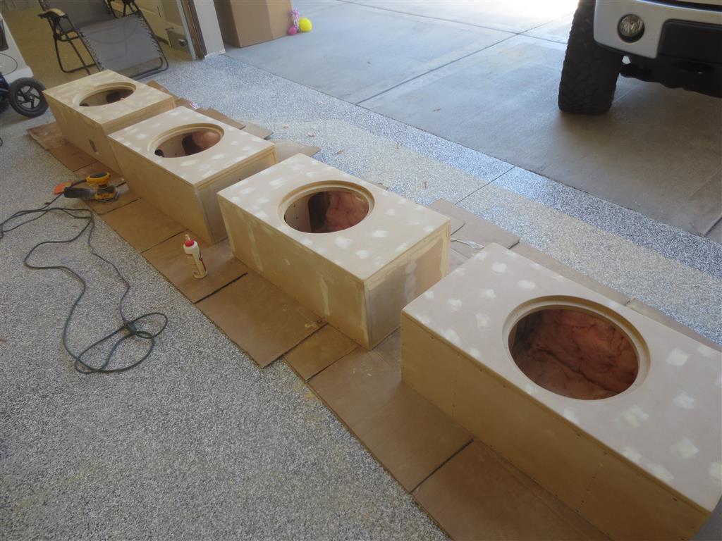
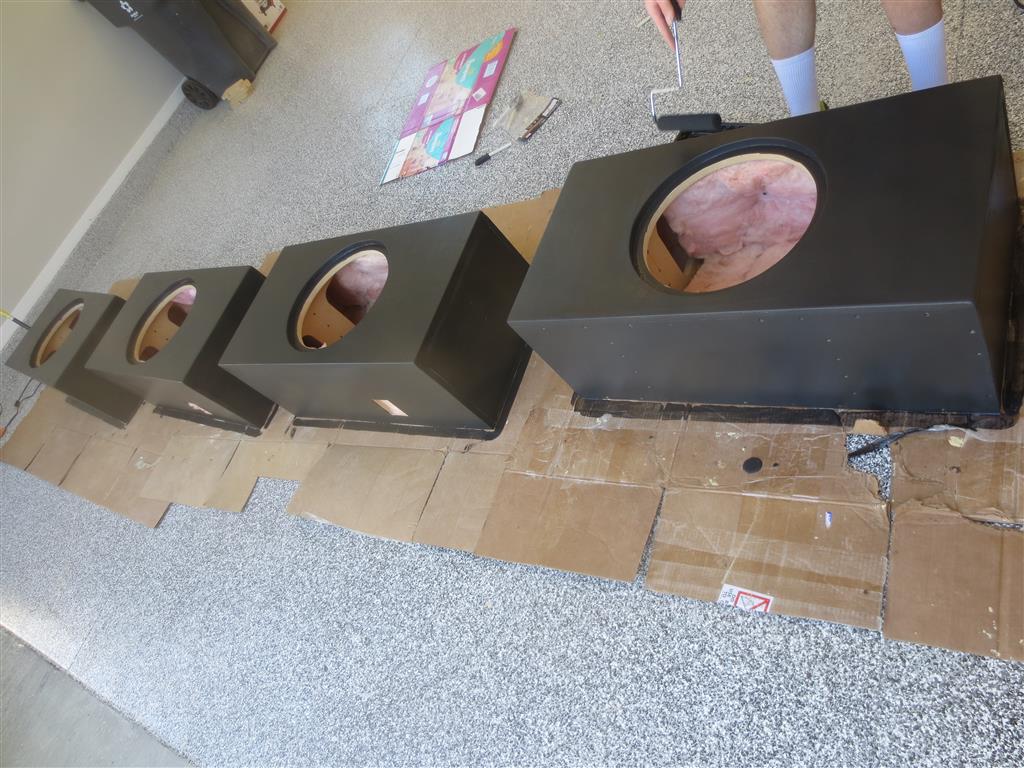
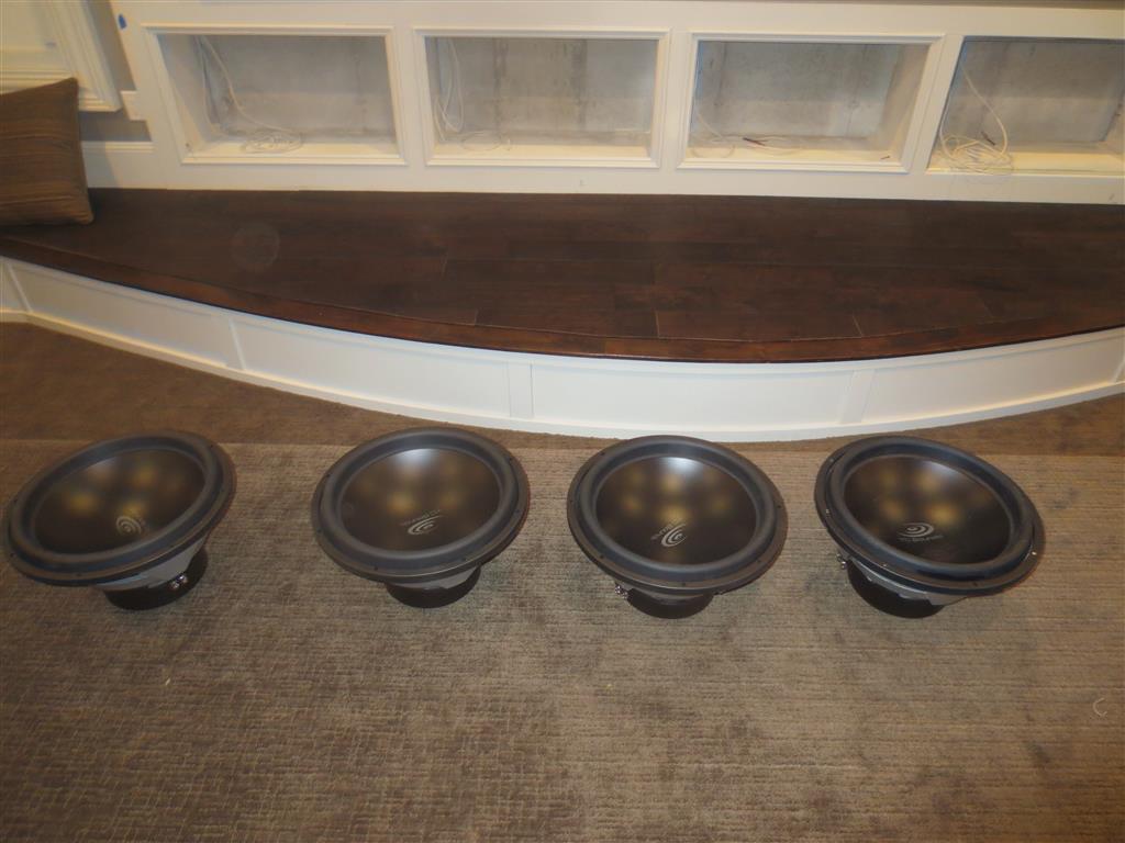
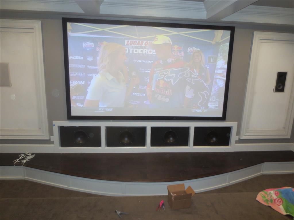
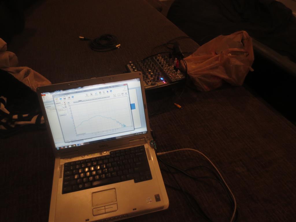
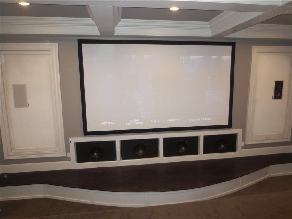
 Last month I flew to Utah to help my brother Steve build some subs to finish out his sweet basement home theater. After months of design and indecision we settled on a concept that we both felt would best suit the home theater and provide a rocking movie-going experience. And this is the design, start to finish, in a nutshell. Without too much extra blabbing by me, here it is…
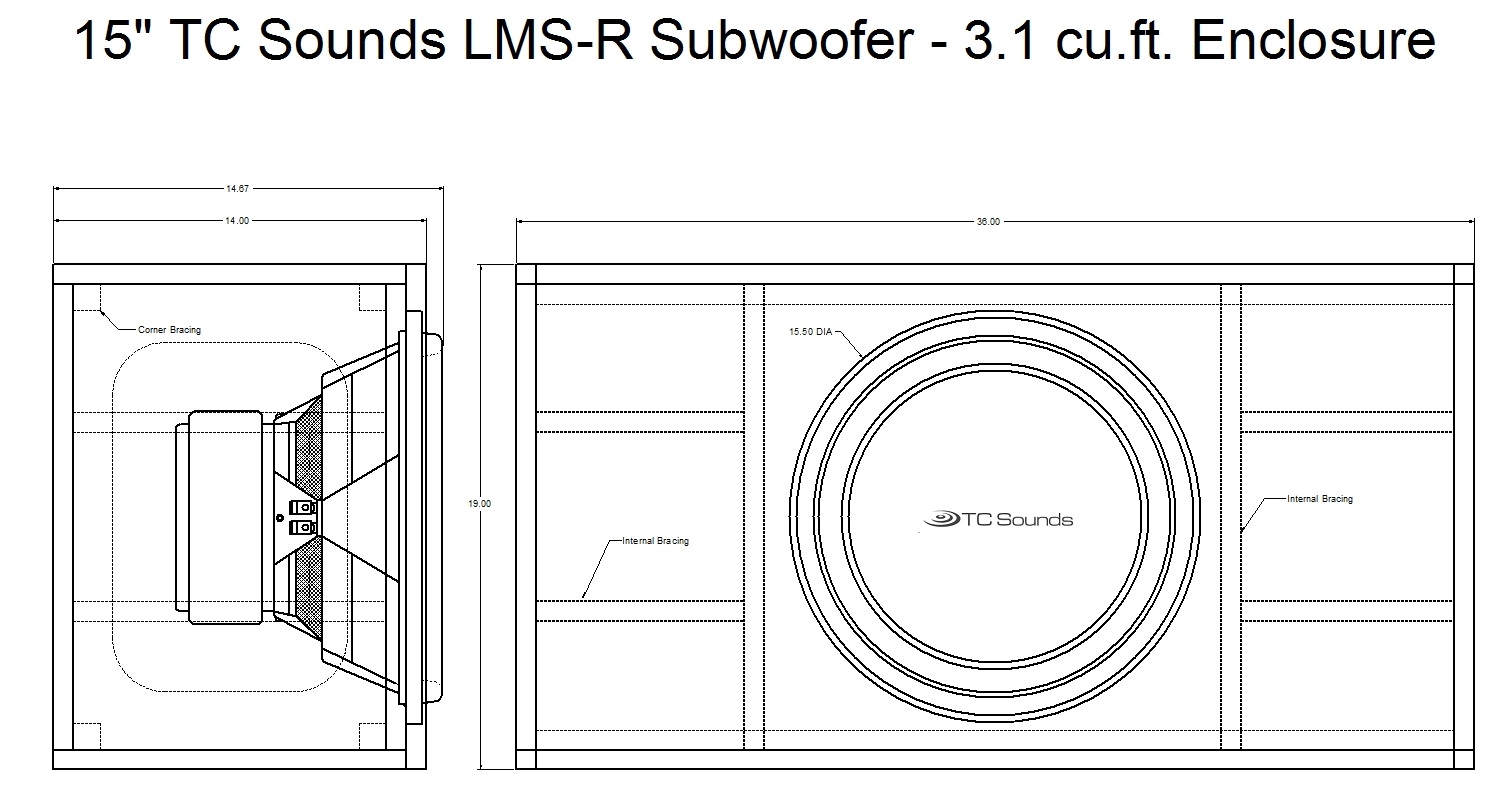


 So we finally got around to getting at least one wall of the den/office completed. When we moved into the new house last year I had just thrown the computers on the floor with a couple pieces of particle board which sort of made a cheesy desk and called it good. Far from aesthetic but
  I cut one of the strips at about 2″ and ran it the length of the wall on top of the existing baseboard (which I did not remove) to give it some added height and to create somewhat of a bottom rail. The total baseboard height is about 5″ from the carpet so it looks a little better and gives a nice clean edge for the battens to run into. Next I cut seven boards at 39″ and placed each one on top of the 2″ bottom rail above the baseboard. I took the 1-3/4″ piece that was left over from the bottom rail and added it to the top along with a piece of the 3-3/4″ making the top part, the top rail, 5-1/2″ wide. Then to give the molding some depth, I routered a custom top rail to go over the 1/4″ piece and ran it the length of the wall. Since this piece ran into an existing door casing (that was only 1/2″ deep) I ended up doing a 30 degree chamfer to bring the 1″ top rail down to a 1/2″. It looks fine to me, though a real craftsmen would probably scoff.


 This past weekend I built a small under-cabinet mount for our XBOX 360 Kinect. This sweet little shelf moves the sensor from above the shelf in the entertainment center (in front of the center channel speaker) to just below the shelf and tucks it neatly out of the way. The wire is more hidden now too and it looks much less thrown-together than it did before. I don’t think this post needs much detail, as the pictures pretty much speak for themselves, but I’ll add some words for anyone looking for a quick fix to clean up their Kinect integration into their media center.


 Last year we bought a new home, while the details of that little adventure are better left for another post, I did want to share some of the work we have done in the backyard in order to make it a more kid-friendly place to play. Now the house was everything we could have wanted, but the backyard left a lot to be desired. There was plenty of space, it had potential, but there was nothing back there but dirt, rocks and one of the hugest piles of sand I’ve ever seen outside of Zuma Beach. The first thing on the list of things to do in the backyard was – put in a play set.


