|
10Triple10 is Born
I started imagining
this design a few months ago (cerca 1999) while I was reflecting upon the
many recent discussions regarding passive radiator operation.
Especially thinking about Deon Beardon's The Beast 18" subwoofer
which uses a single 18" active driver and (3) 18"passive radiators.
So I made up this little sub I call The
10Triple10.
When Four is Better Than One
This subwoofer is a
10" woofer in a small enclosure with (3) 10" passive radiators. All I can say about this subwoofer is its performance is
completely remarkable. You'll think that either your eyes or your
ears are deceiving you to believe that a subwoofer this small can produce
such enormous amounts of truly deep bass. This sub loves low
notes. It's just
playing along having a good time up above 40 Hz, but when those notes
start to get into the 20's, it's like the sub drops into overdrive.
So anyway, enough salesman talk, here's the real deal on the design,
production, and test results of my all-mighty 10Triple10
Subwoofer.
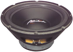
The Driver
The speaker starts
with Ultimate Attitude's 10" AU1040 subwoofer. A sub designed for
car audio, but since I haven't seen many inexpensive home theater subs in
the 10" range on the market for DIY, I went ahead with this sub. The
specs are listed here: Attitude AU1050 10" Stamp Frame Woofer. 250
watts RMS/350 watts max *Impedance: 6 ohms per coil *Frequency response:
25-200 Hz *Magnet weight: 50 oz. *Fs: 29 Hz *SPL: 89 dB 1W/1m *Vas: 3.50
cu.ft, *Qms: 8.20 *Qes: .45 *Qts: .43 *Xmax: 9.9mm. *Net weight: 9 lbs.
*Dimensions: A: 10-1/16", B: 9-1/8", C: 5-1/16", D: 5-1/4", E:
1-1/4".
The Passive Radiators
The passive radiators were custom built
from flat pieces of
machined MDF with a large thick foam surrounds. Each PR has an Xmax of
around 10 mm. These diaphragms originally would have gone
into making a full-blown PR, but I got to them before they made it that
far down the assembly line (in a sense). So we're talking really
cheap flat PR's but with nice thick surrounds and a solid machined MDF
diaphragm. Each PR had an initial mass of 90
grams.
Modeling the Enclosure
To the right are a
few thumbnails of shots taken from Brian's ported.xls. I
wanted the box to look proportional with the (4) 10" speakers on each
side. A cube seemed the logical choice. I didn't want too much
extra space on either side of the woofers either. So I decided on
15" all the way around and plugged in the T/S parameters into a few
programs to see if this driver would work in a 1.35 ft^3 box. A lot
of times you can get away with making the box smaller than normal if you
can tolerate a hump in the frequency response and higher f3. In this
design, I can get rid of any hump by tuning the box
much lower than would normally be possible with an ordinary port.
Small Box + Low Tuning + PR = Lower Hump in FR. So here's the final Frequency
Response Plot, SPL Plot and Excursion Plots of the 10Triple10.
Tuning Frequency
I deciding on a tuning frequency of 30 Hz,
since that dropped the hump from +3 dB to only +1.3 dB. I could have
gone as low as 25 Hz for the tuning and probably had acceptable results as
well. But I wanted to keep from having to add too much mass to each
PR. I was afraid that if they were too heavy, they'd cantilever.
Adding mass to a
flat PR was tricky, I didn't want to weigh down
one side more than the other making it
"lopsided". I used 9 washers that weighed 18 grams a piece to mass
down each passive.
How to Calculate Tuning Frequency of a PR
System
So how did I know to
add (9) 18 gram washers? I used passive.xls which is available
here at my site. I entered in the parameters of my
passives and the fB and size of the enclosure. I found Sd by
measuring across the diameter of the PR plus 1/3 of the surround on either
side. This came out to be really close to 7.50" See the
picture to to the right. Although you can't see what the ruler says, this
shows how it is possible to find the Sd of a driver or PR. Sd =
pi*(D/2)^2. Then do the proper conversion to cm^2 or m^2. So from the spreadsheet it looked like I
would need to add 160 grams (for a total of 250 g) to each PR for a tuning
of 30 Hz in a box totaling 1.35 ft^3. And that was that. Now it was time to build the box and put the PR's
together. I won't go into any detail on box construction. But you can see quite easily from the pictures how the box
was made. 3/4" MDF with 1/8" mahogany plywood and a rad slab of
green marble on the top framed by a black border. It's stained in Light American Oak from
Minwax.
The Pictures
To the right you'll find pictures of the last
stages of building this subwoofer. That's all I have to say for
now.
From an initial comparison, this sub was keeping up with a single Shiva in
a 3 ft^3 ported enclosure. Now that was an amazing thing to
hear! Though it didn't have the volume.
The Results
After I put the
box together and screwed in all the speakers, I did an fB test to see if I
hit my targeted 30 Hz and lucky for me I hit the 30 Hz perfectly. Just
a little bit of info regarding how the frequency response was
measured. The sub was measured in my front yard so as to avoid all
reflections from walls and ceilings. This is about the best
anechoic response you can get. Only the ground is capable of
interfering with the results. I used a precision frequency
generator, frequency counter, amplifier, and my trusty Radio Shack
analog SPL meter. The sub was placed in the grass as far way from
the house and any walls as possible, while the SPL meter was placed at
exactly 1 meter from the front baffle at the same height as the dust
cap. I ran 9.75 volts into the driver which has a nominal
impedance of 3 ohms which roughly equates to 31 watts. 31 watts is very conservative but even still I was
able to get the PR's to cantilever at 30 Hz and below. I then plotted
the SPL at 5 Hz increments starting at 15 Hz working my way up to 100
Hz. I accounted for meter correction and plotted the results
in Excel. That is the graph you see to the right. In-room
response of the sub would improve the low end some. The
extra hump you see below 30 Hz I believe was due to a loud knocking sound
that the PR's began producing as they began to cantilever.
Now this was just
using a pure sinewave, not your typical bass material you'd get from a
movie or even most music. When watching movies the passives do not
move enough in a consistent motion to begin this rhythmic cantilevering
action, they actually behave fine and cause no problems. The biggest
drawback to this design in the 10" driver bottoms out easily at low power.
Explosions and car crashes cause the drive to "pop" badly.
But he driver is pretty crappy and a
30 Hz tuning doesn't help. Any content below 30 Hz will drastically
cause the driver to exceed its Xmax. For future designs, tuning
needs to be closer 20Hz and the driver needs more Xmax. |