
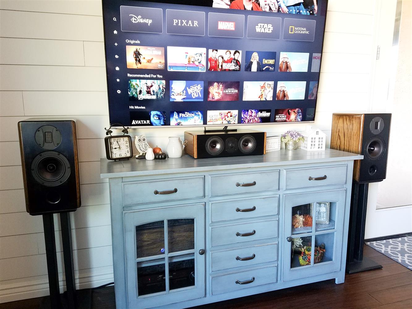
 Shortly after completing my Dayton HiVi RTS181.3 speakers, I got to work on a matching center channel to finish off the front sound stage of my family room theater. And this weekend, after approximately 10 weeks since I started this little speaker project, I can finally say it is now complete! And what can I say about how it sounds? Well in a word, it sounds fantastic! And just in time to binge watch all of our favorite Disney movies on Disney+ to boot! As with most of my speaker builds, here’s the matching blog to describe the design and build process in its entirety, show of some pictures, talk about the crossover, show some response plots and give my overall thoughts on this speaker for anyone out there hoping to design and build something similar. This is an awesome center channel speaker, so far everything I have watched sounds neutral, clear, detailed and all around very good. Read on to find out more.
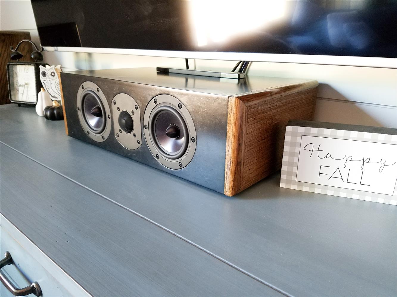
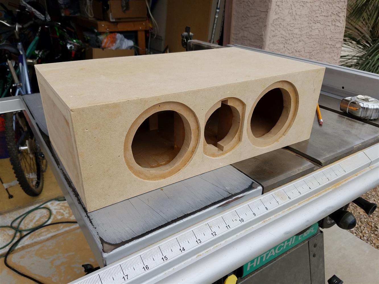
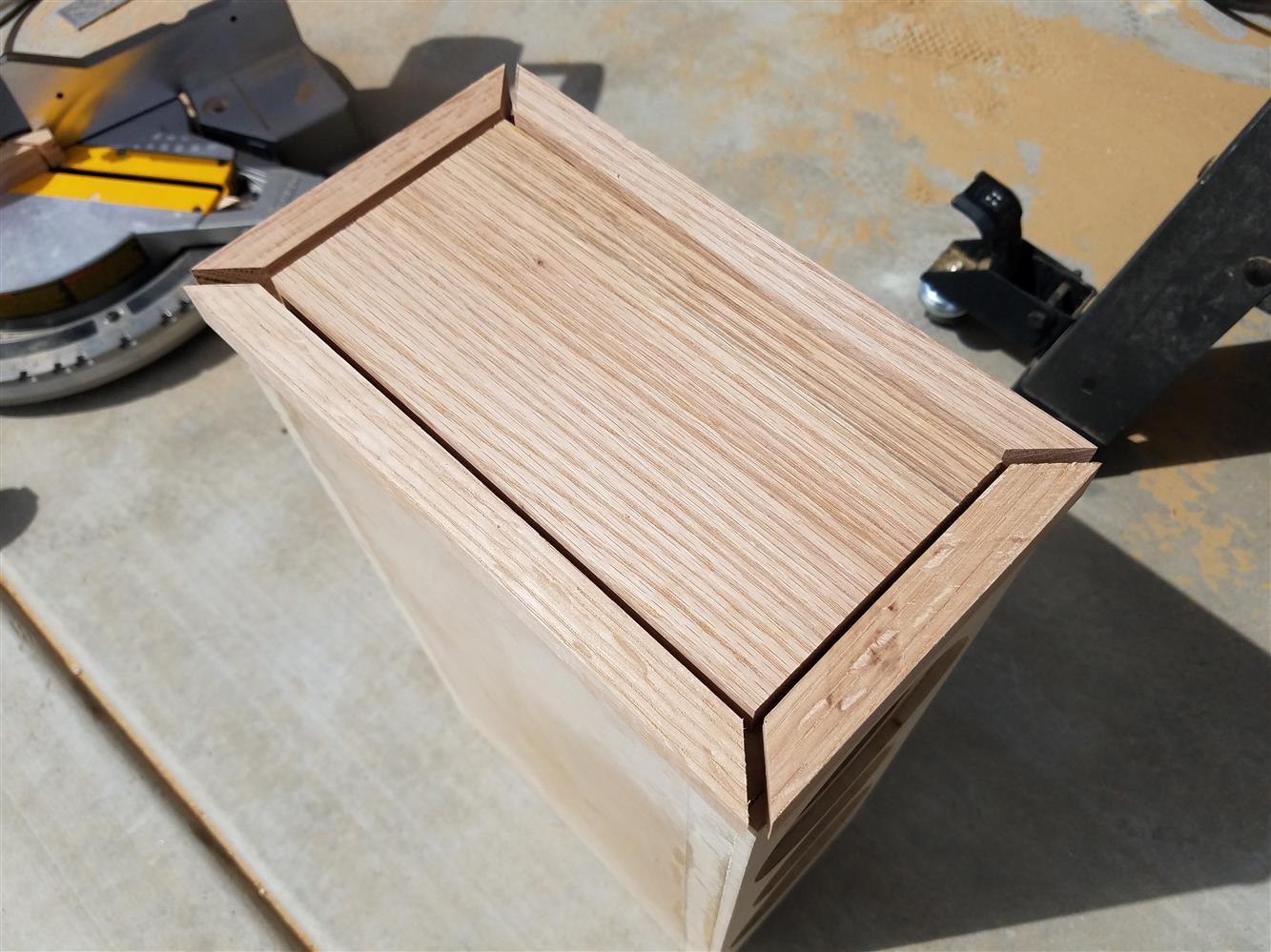
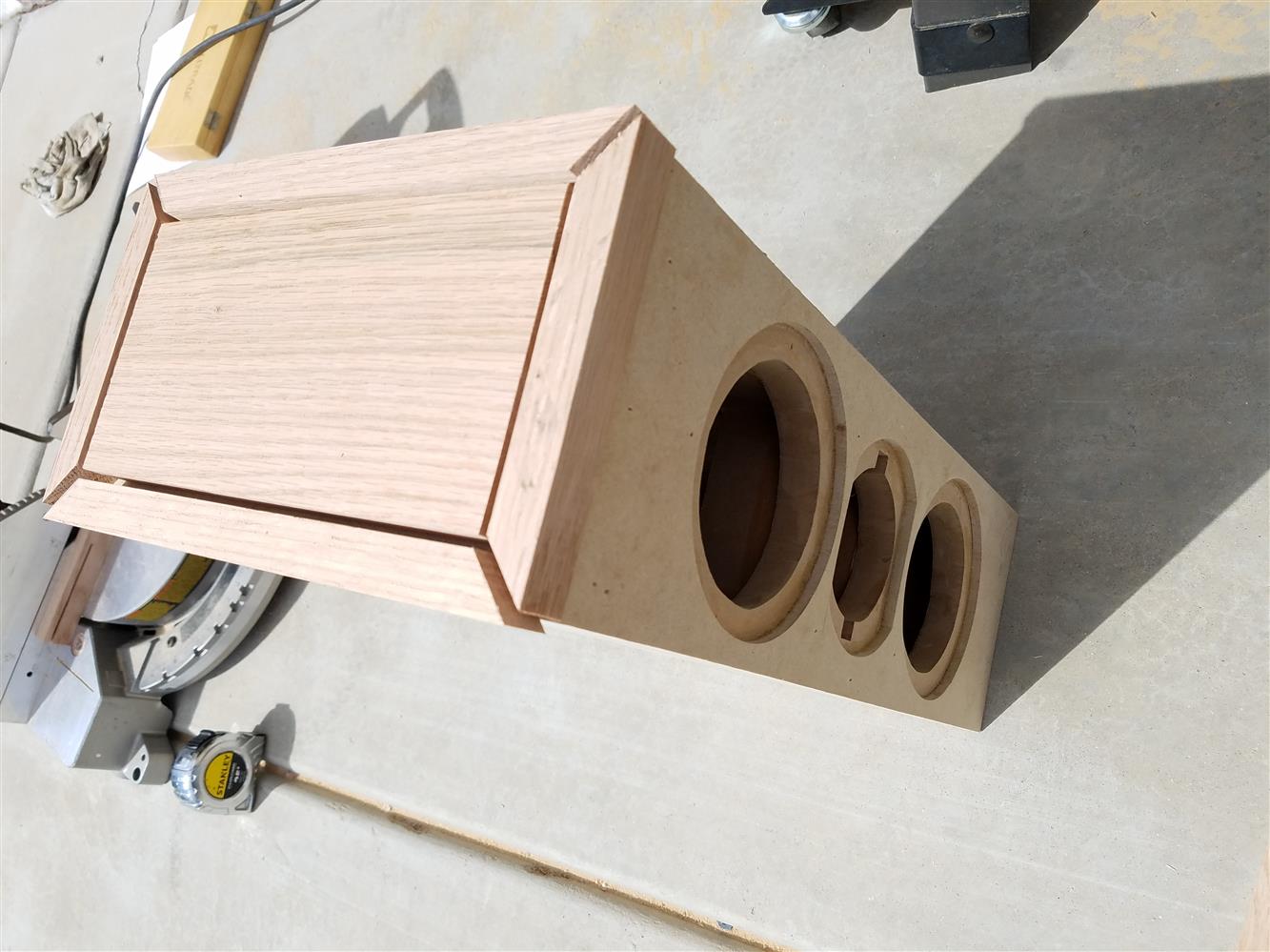
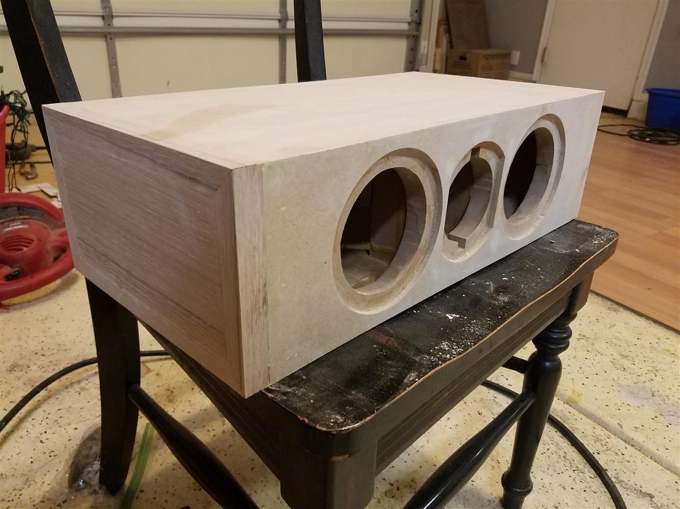
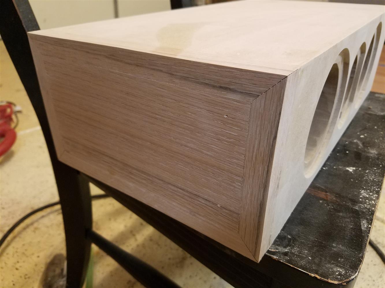
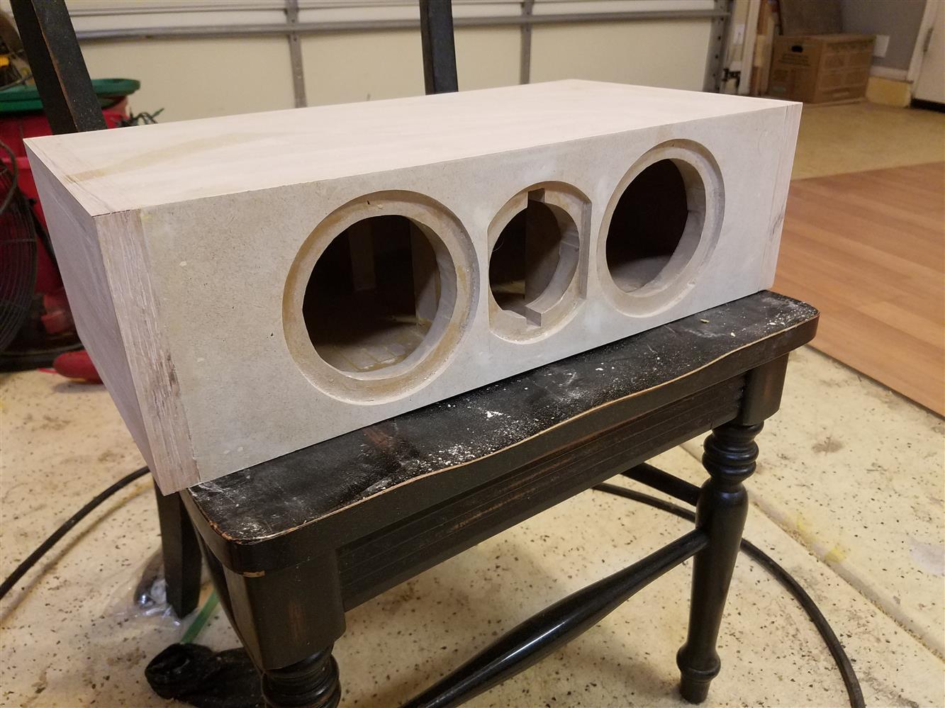
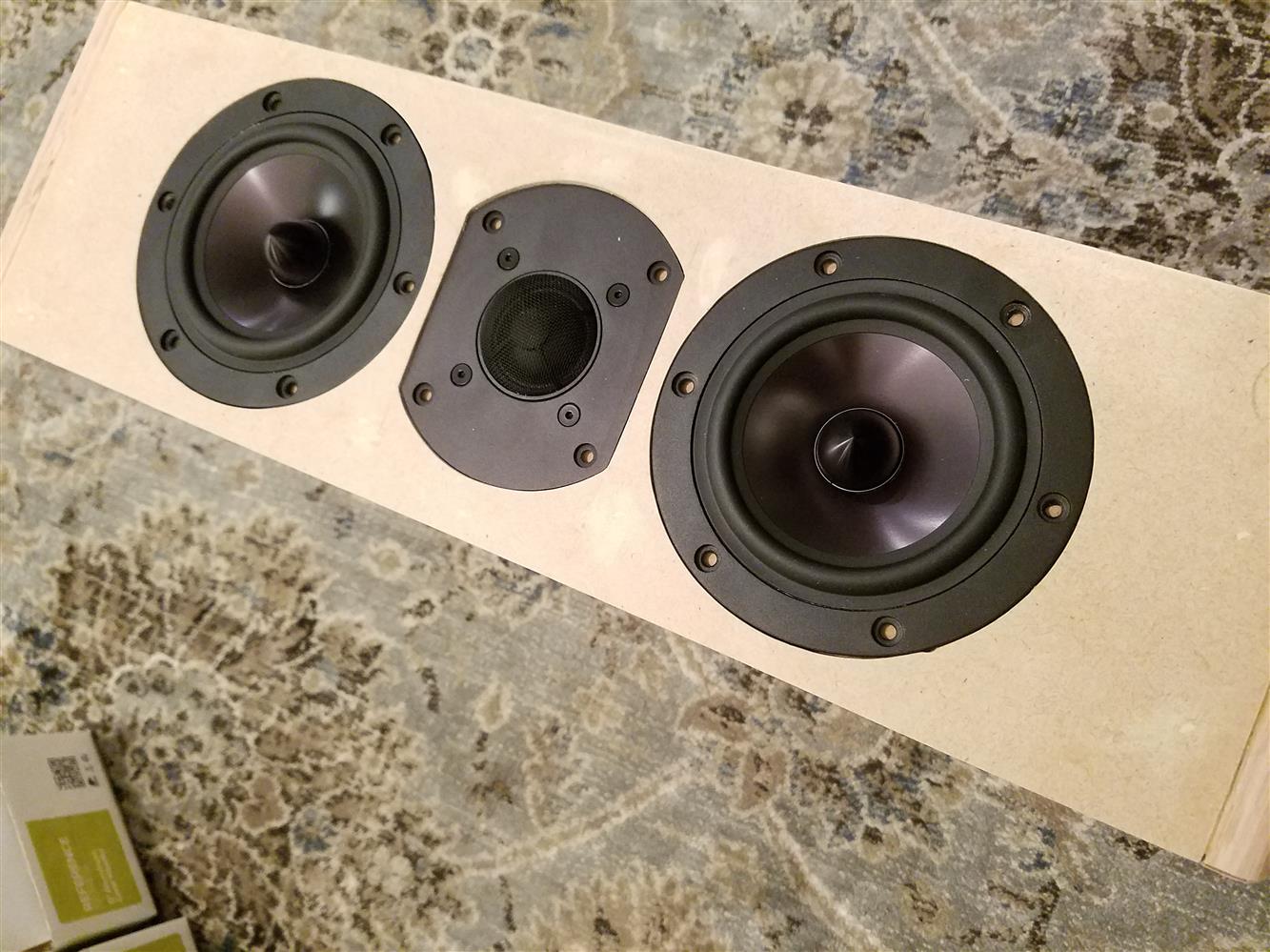
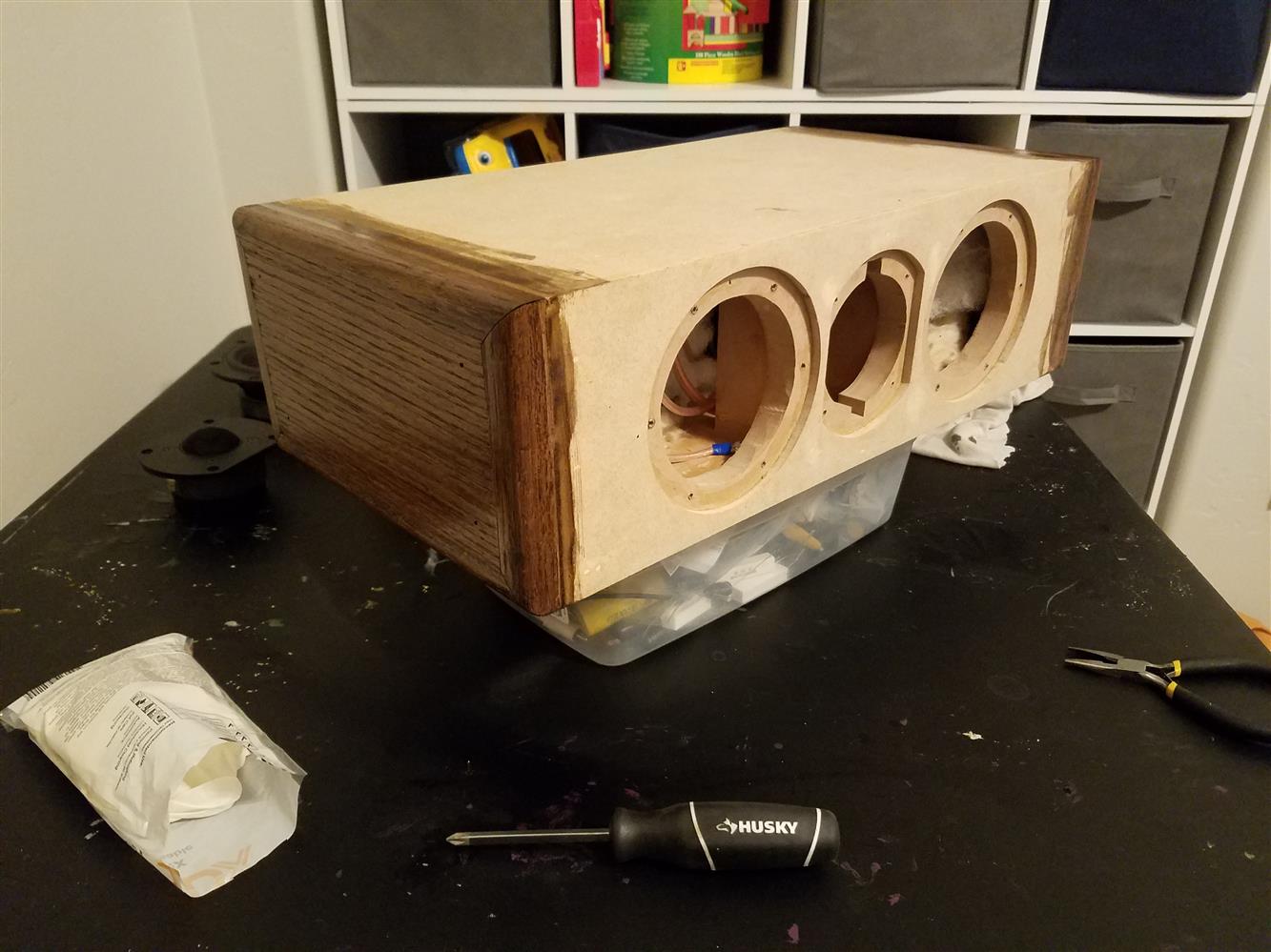
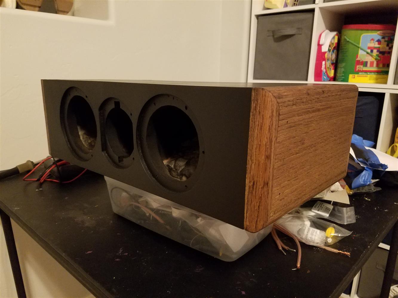
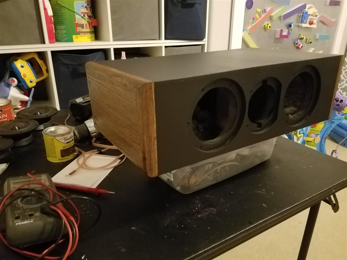
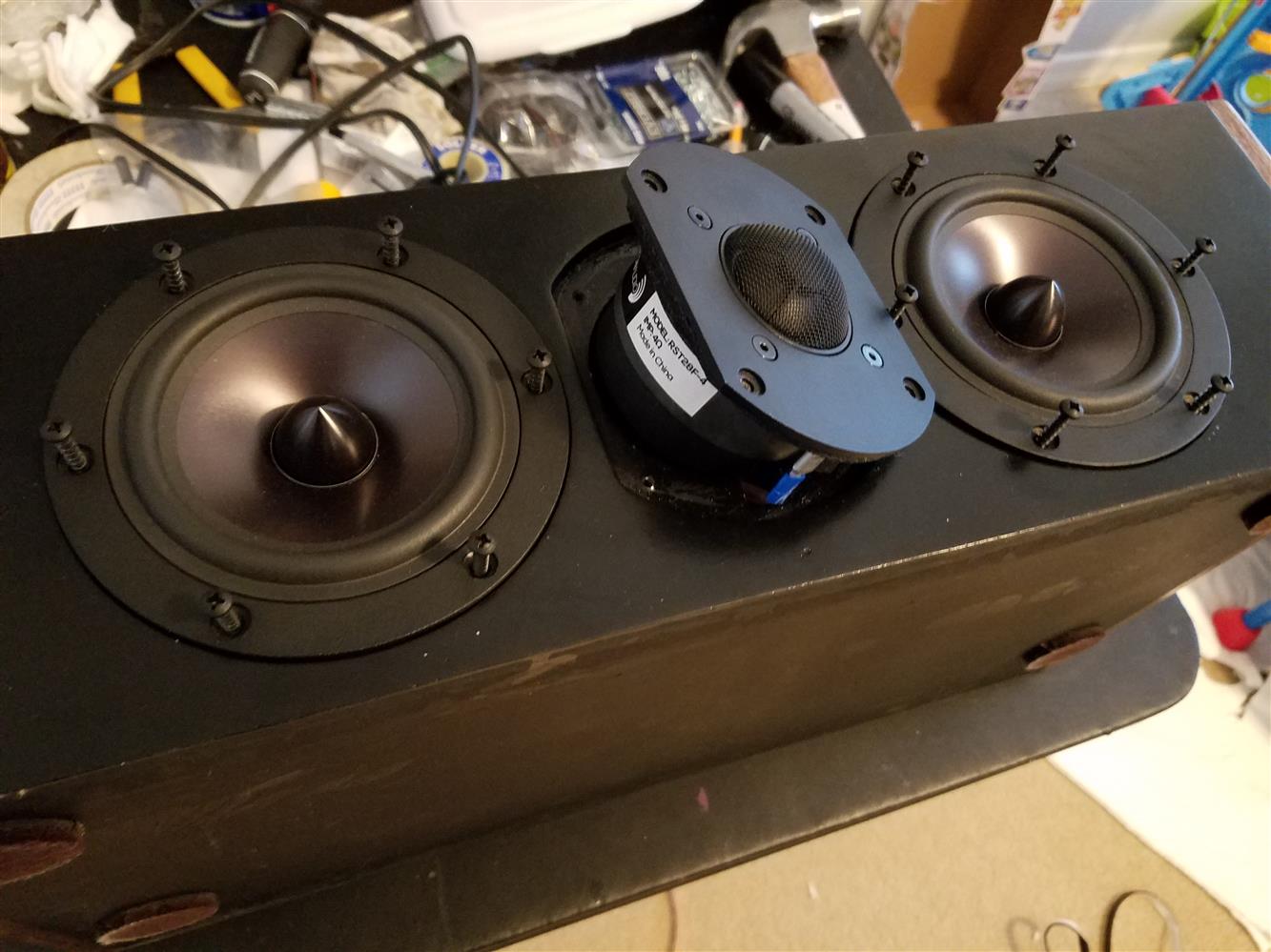
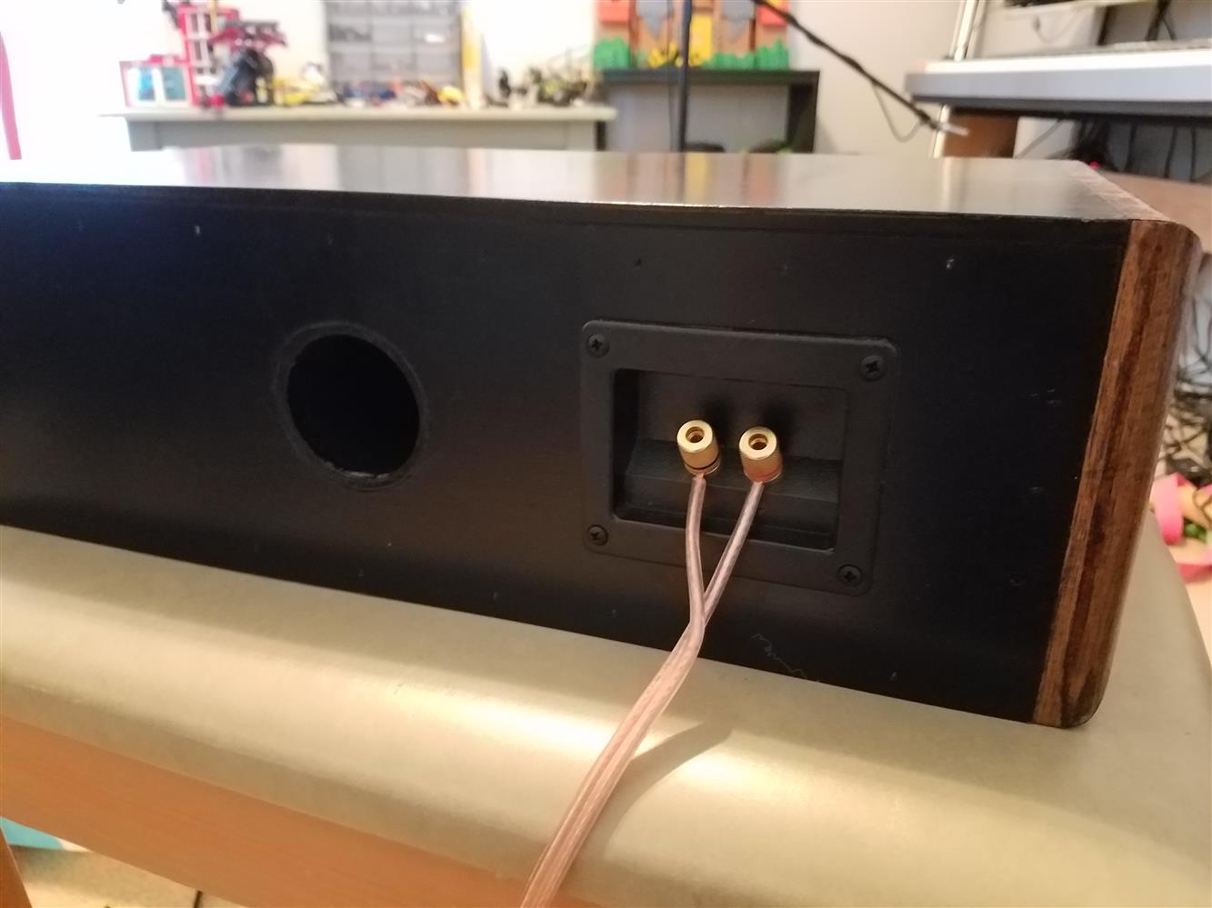
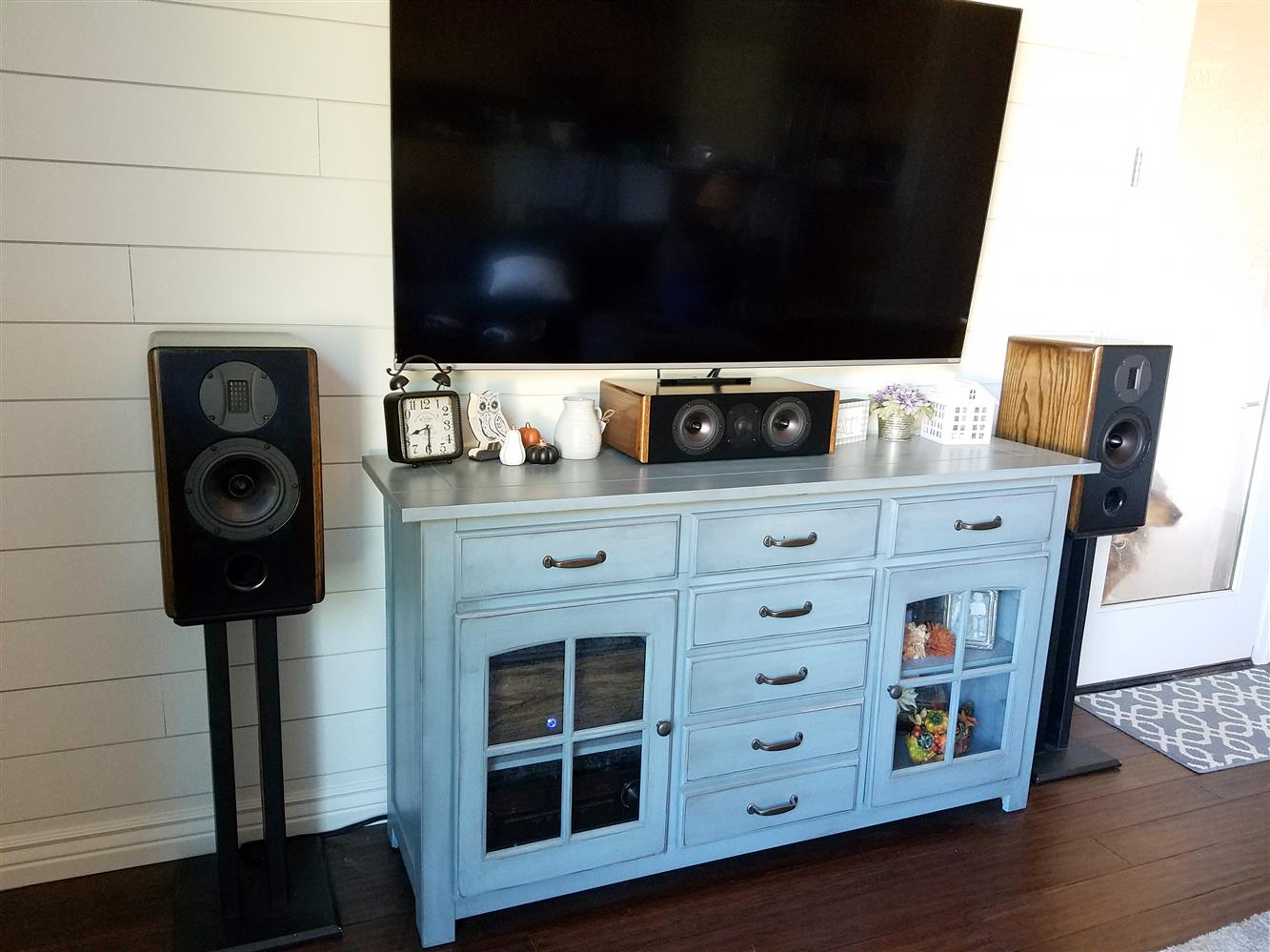
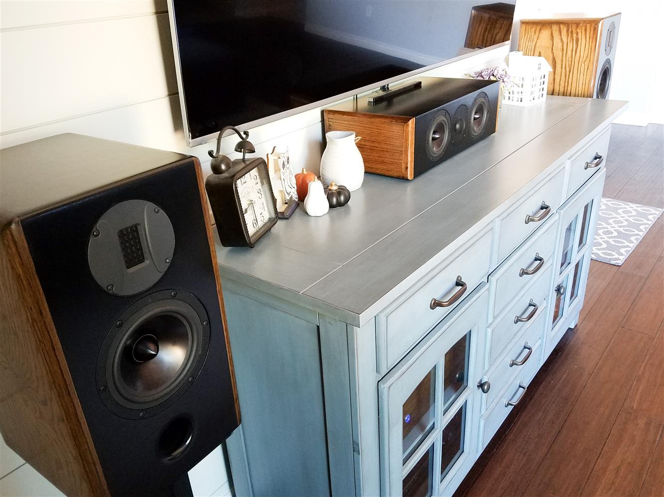
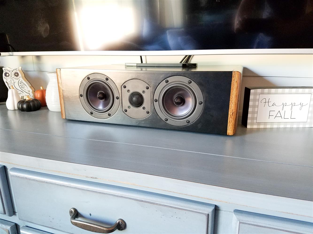
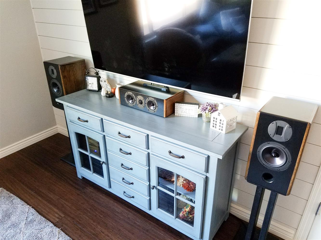
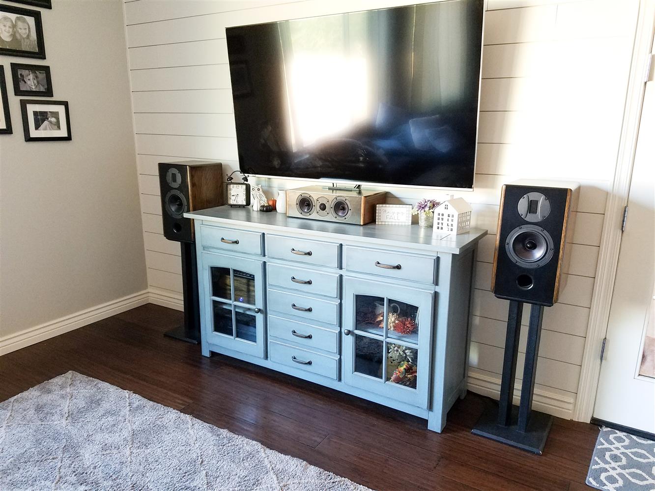
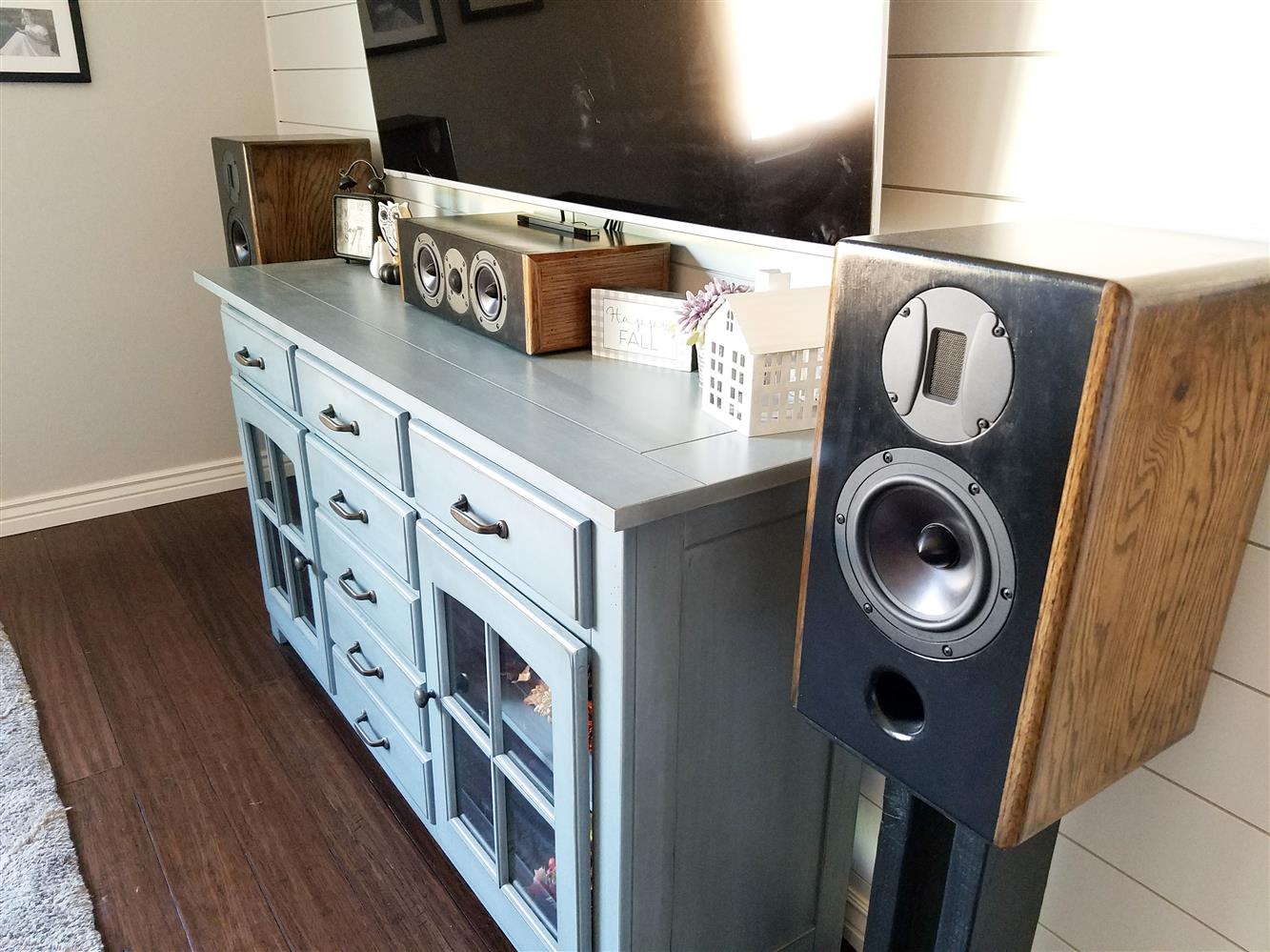
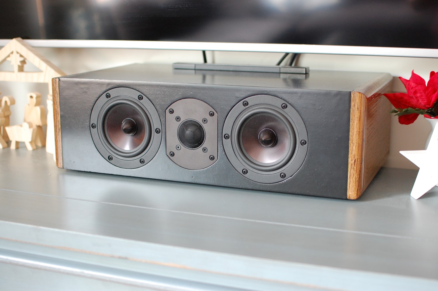
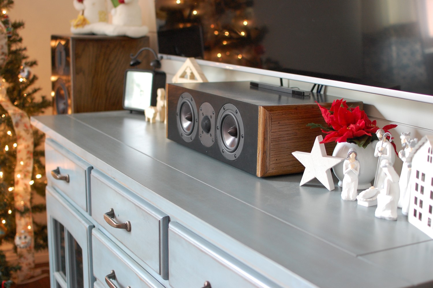
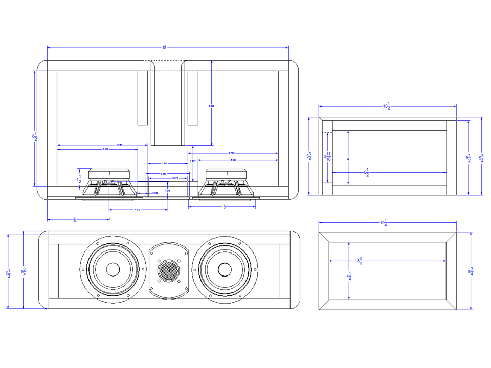
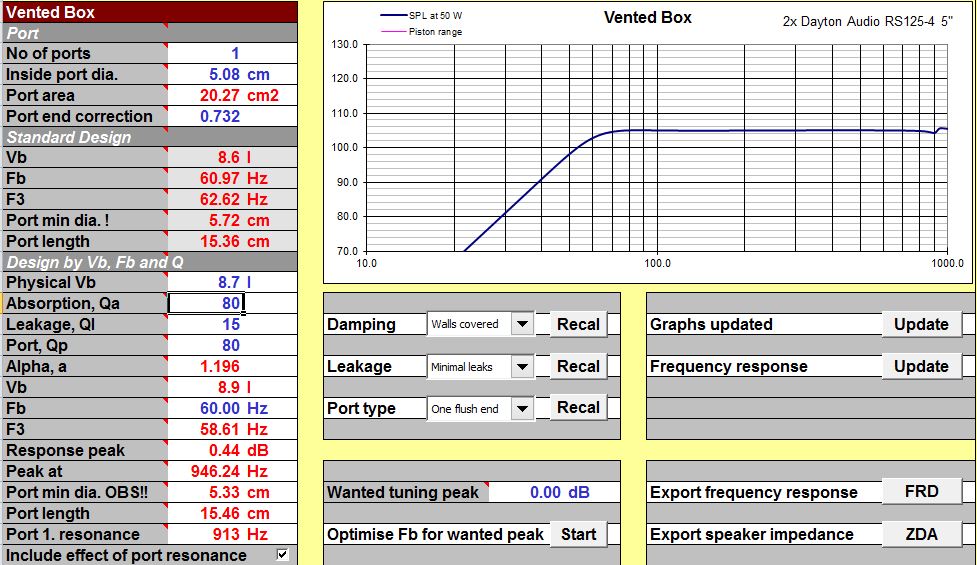
First off, some quick stats: the Dayton Reference 2-way center channel speaker consists of a pair of Dayton Audio Reference RS125-4 5″ aluminum cone drivers matched with the RST28F-4 1-1/8″ soft dome tweeter in a horizontal MTM configuration. The enclosure is made from 3/4″ MDF with solid 3/4″ oak side panels for a decorative, classic look (and to match their complimentary LR speakers). The cabinet is 19-1/2 x 5-1/2 x 10 inches (WxHxD) which equates to about 8.7 liters with a 2 x 6 inch port which results in a 60 Hz tuning frequency and an f3 of 58 Hz. This is an optimized cabinet volume for a pair of RS125-4 drivers resulting in a maximally flat response though excursion below tuning needs to be kept in check. This speaker will perform best when used in a home theater environment with the receiver settings set to SMALL or at the very least with a high-pass filter set no lower than 50 Hz. The crossover is a fairly simple 12 dB/octave topology on both the woofers and tweeter centered around 2,700 Hz with a fixed L-pad on the tweeter (and a notch circuit to tame a response peak at around 15 kHz). A total of 12 elements are used made up of air core inductors, metalized polypropylene capacitors and non-inductive resistors. A 5-way binding post speaker terminal mounted in the rear provides easy connection to the receiver. The cabinet walls are lined with 100% cotton batting and the cabinet is 50% loosely stuffed with 100% polyfil stuffing. And that’s about it!
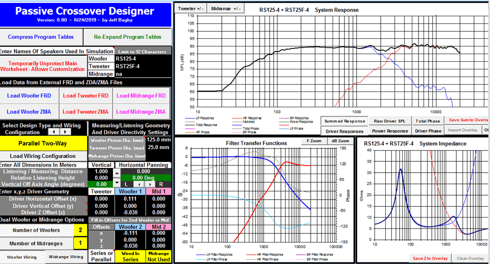
Okay so let’s get right down to the nitty gritty of this speaker project – the design. I went through many of iterations of center channel concepts before ending up on this one and I know what you’re thinking, you’re thinking Dan, this is a basic, no-frills, run-of-the-mill, crappy, horizontal MTM speaker that’s going to suffer from all the same problems every other cheap horizontal MTM center channel speaker suffers from, what do you mean you spent hours and hours designing this thing, it looks like it took you 5 seconds to plop those three drivers into place, this is boring, I’m outa’ here. And you’d be mostly right, this design is arguably flawed at the outset in that it suffers from poor horizontal off-axis response due to overlapping sound waves from having two drivers spaced 8 inches apart from each other on the front baffle and producing the same frequencies. This effect (typically referred to as lobing or comb filtering) can be easily be verified by modeling this driver layout in a crossover simulation tool such as Passive Crossover Designer (PCD).
 But before we get to that, I had designed on paper a wide variety of other driver layout combinations that perform much better than this design in both frequency extension, power handling and off-axis performance, but still I ultimately settled on this one for a variety of reasons which I will get into. This is where we come to the part about DIY speaker building that I love so much. Every speaker design has its strengths and its weaknesses. Every design has inherent constraints that must be managed and balanced. My constraint isn’t your constraint. What looks good doesn’t sound good and what sounds good doesn’t look good. And so on and so forth. I simulated tons of driver layout combinations using PCD for horizontal off-axis response and basically came to this conclusion: the absolute ideal layout for a center channel speaker when it comes to horizontal off-axis response is to use a single full-range driver or a point source. Every other design that deviates from this is a compromise with respect to ideal off-axis response.
Since full-range drivers in and of themselves are a compromise in other ways, that design choice would simply trade one limitation for another. And while super-flat off-axis response plots look great when showing off a speaker’s performance in audio forums and with your audiophile friends, its real word benefit is far less practical, in my opinion. At least with respect to center channel speakers in a home theater environment. I believe better off-axis response has far more merit in two-channel audio listening environments than anywhere else. But when it comes to a center channel speaker playing dialogue from a movie, how critical is having ruler flat off-axis response? Is it because of poor ole’ Grandma sitting in the far corner seat on the couch constantly saying, “What he’d say? What’s going on? I can’t understand anything they are saying”. Everyone else will just think Grandma needs to turn up her hearing aid, but you will know the truth, the real reason she’s oblivious to the movie’s plot: your crappy MTM center channel puts a massive null in the frequency range of human speech right at that spot on the couch where Grandma likes to sit. If only you’d forked over a few more bucks for a bigger, better center channel, perhaps a 3-way design that aligns the tweeter above the midrange driver and uses two woofers with a crossover frequency that’s nice and low so as to minimize the effects of comb filtering, then maybe Grandma would actually know what’s going on during movie night for a change.
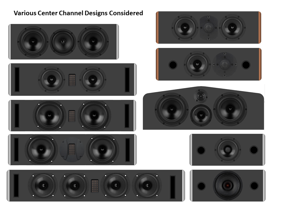
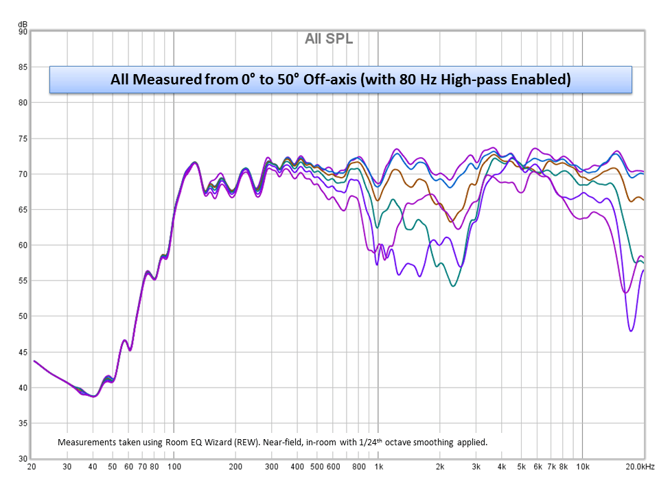
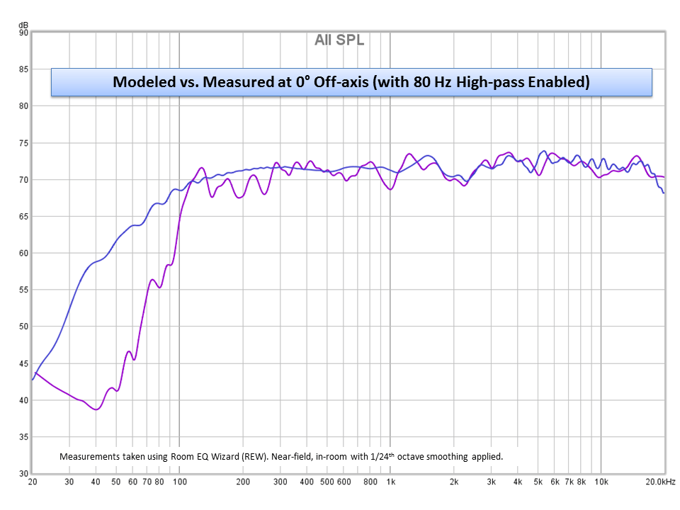
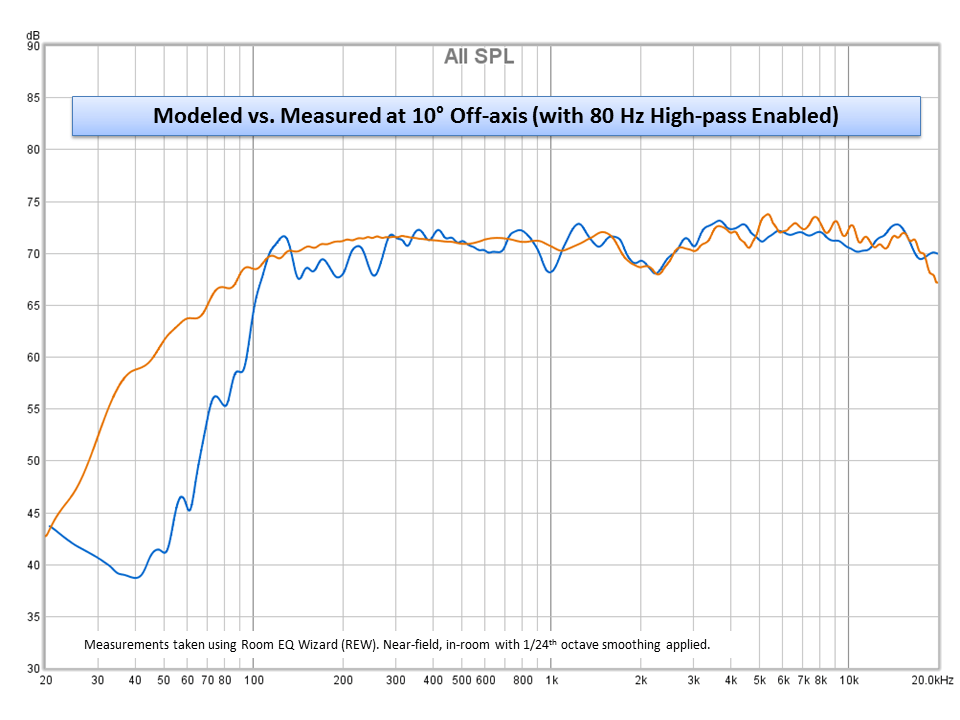
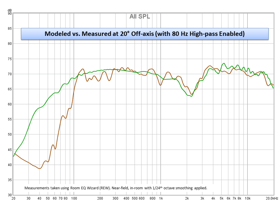
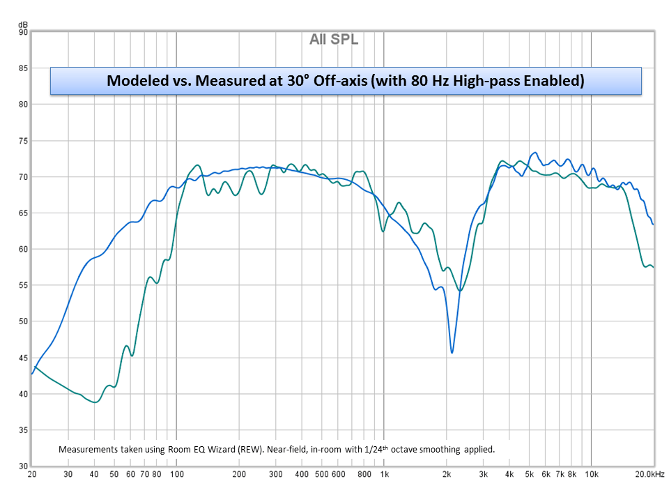
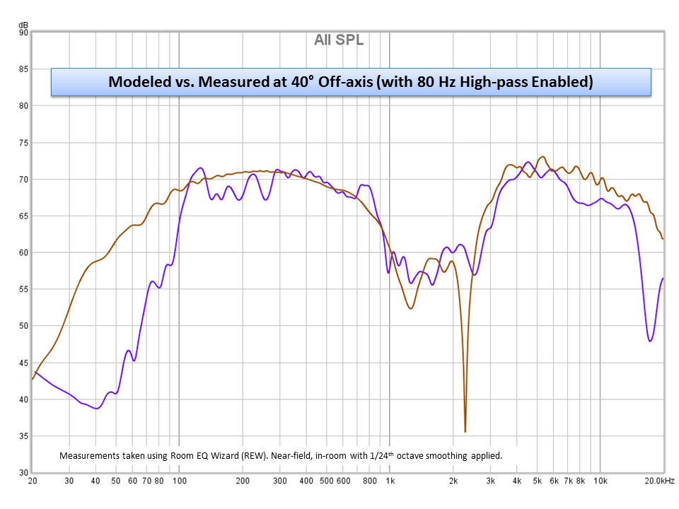
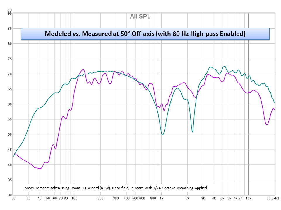
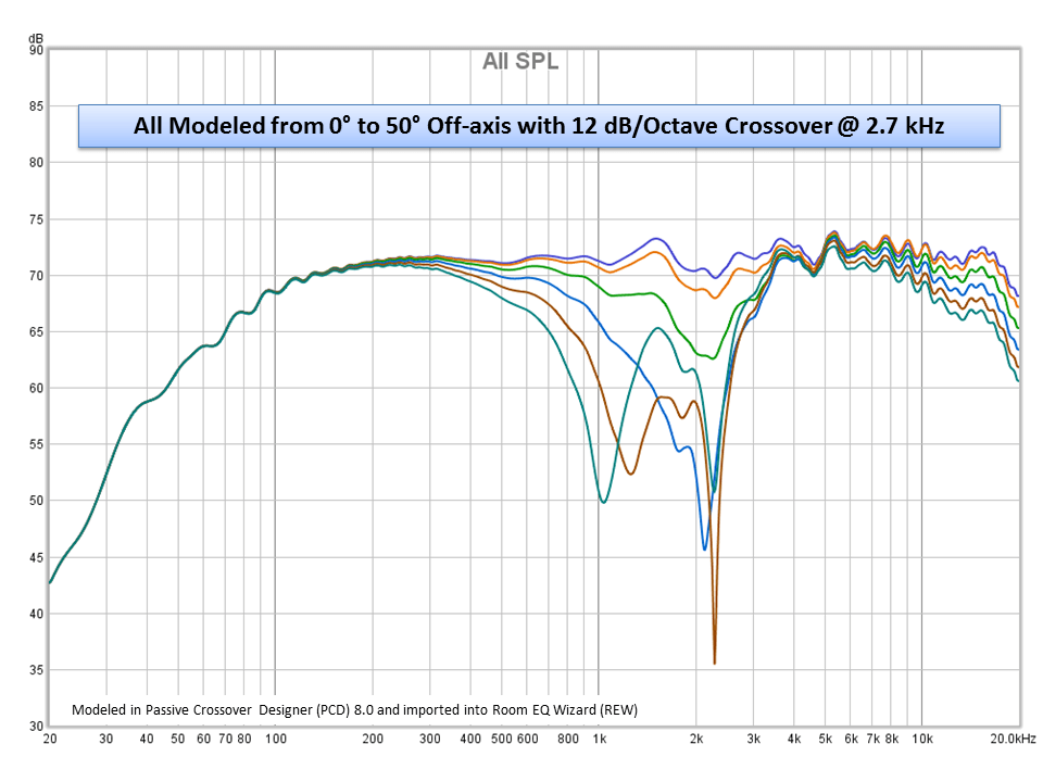 That’s okay, I’m not going to lose sleep over building an MTM speaker and flipping it on its side into its worst possible orientation because ultimately there are far more reasons for movie dialogue to be unintelligible than a little off-axis comb filtering. It’s true though, in free space, or measured near-field, the off-axis horizontal response of an MTM flipped on its side is pretty abysmal. Which can be confirmed in both simulation and in real-world measurements. See the various graphs I’ve shown here that showcase this effect in both simulations and in measured data for this speaker. So what can be done about it? And does it really matter? So first and foremost, the best way to combat poor off-axis response is to change the layout of the drivers. Go point source, as mentioned above, or coaxial with the tweeter inside the woofer, a design KEF capitalized on years ago which has done them very well. More recently Parts Express has started to offer some inexpensive coaxial drivers for those aiming for that truly point source sound. If I were to build another another center channel today, I would probably like to do a 3-way using that Dayton 4″ coaxial driver paired with a set of RS150-4 woofers à la Elac’s Uni-Fi UC5. I drafted up this design and it looks pretty awesome (see pic above, top left image). I wish PE offered more coaxial options that like. But if none of those options suit your fancy, then a regular MT speaker with the tweeter above the woofer is the next best layout option. Even if it doesn’t “look right” sitting underneath your TV, it will have very good horizontal off-axis response. Just behind that is the same MT speaker but rotated on its side. In this case you swap horizontal off-axis performance of a typical 2-way speaker for its vertical performance. Still not a bad deal if you’re in a pinch but definitely better than a straight horizontal MTM layout.
The next best option is to go MTM but design the crossover as a 2.5-way. This way you get the nice bass response of dual drivers, but you set the crossover point for just one of the drivers much lower, say only a few hundred Hz, so that only one driver is producing frequencies where comb filtering typically starts to become a problem. With only one driver producing the higher frequencies, the setup behaves more like an MT on its side but has the benefit of additional sensitivity at the lower frequencies, better power handling and increased bass performance due to the dual drivers. One of the best layout options that is becoming more and more popular is one that basically combines the two previous designs into a single 3-way speaker with the tweeter above the midrange and a pair of woofers on either side. The midrange and tweeter behave like an MT rotated vertically (yeah) and since you’ve got that dedicated midrange that can play fairly low, the two woofers on either side, albeit far apart from each can be crossed over very low so as to where comb filter effects are minimized. Keep the two woofers close enough together with respect to the crossover frequency and lobing won’t be significant at all, or at best, only start to come into play way off axis, beyond 60 degrees or so. Which is completely reasonable for movie and home theater environments. Most TV’s start to look like garbage beyond 30 degrees off axis anyway, so now Grandma can complain about not only not being to hear the people in the movie but how your 4K HDTV with HDR10 looks like crap from her spot on the couch. Guess what, she won’t be wrong! Hey, I can only make so many people happy. Wait until you put a microphone in Grandma’s seat and measure your subwoofer only to realize that guess what, she’s got the most bumping seat in the house! Go figure. Of course she does, it’s in the corner where no one else wants to sit. TV looks like poop, can’t understand the dialogue and there’s so much bass her dentures keep rattling out of her head. I’m starting to think Grandma might not come over for movie night any more.
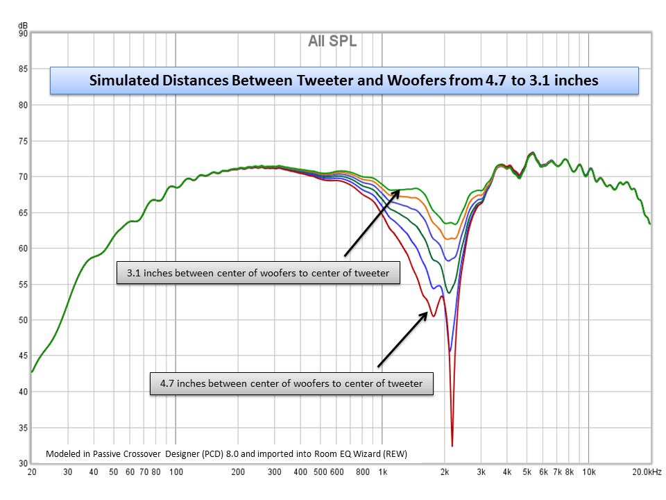
Alright, so I think I’ve covered a few options to optimize the driver layout in a center channel to improve horizontal off-axis response. Note that most of these configurations will also suffer from some amount of vertical lobing as well, but in most cases, the center channel can be placed just about at ear level, or at least pointed at ear level, so it’s not as much of a design constraint I don’t believe for most home/family room theaters. If you have a massive theater with stadium seating then you’ll need to be aware of both vertical and horizontal off-axis responses, in which case actually that last option above probably works the best for that configuration as well. And finally the last and possibly least desirable configuration (on paper at least) is the standard horizontal MTM with a regular 2-way crossover. Off axis response begins to degrade almost immediately off of dead center and at its worst can have 30-40 dB suckouts or nulls in the response from 300-3000 Hz, right in the range of human speech. The best thing you can do to minimize its effect is to move the woofers as close to together as absolutely possible. If they can be touching, perfect. Put a tiny dome tweeter in the little pocket above the frames of the two drivers and you’ll have as close to an ideal off-axis response as is possible in an MTM configuration. But for every inch those two drivers move away from each other, the off axis response suffers that much more. The worst thing you can do is space the drivers out beyond the diameter of the tweeter frame just to “fill the space” or because you think it looks better. Or at least be prepared to do a crazy-low crossover point.
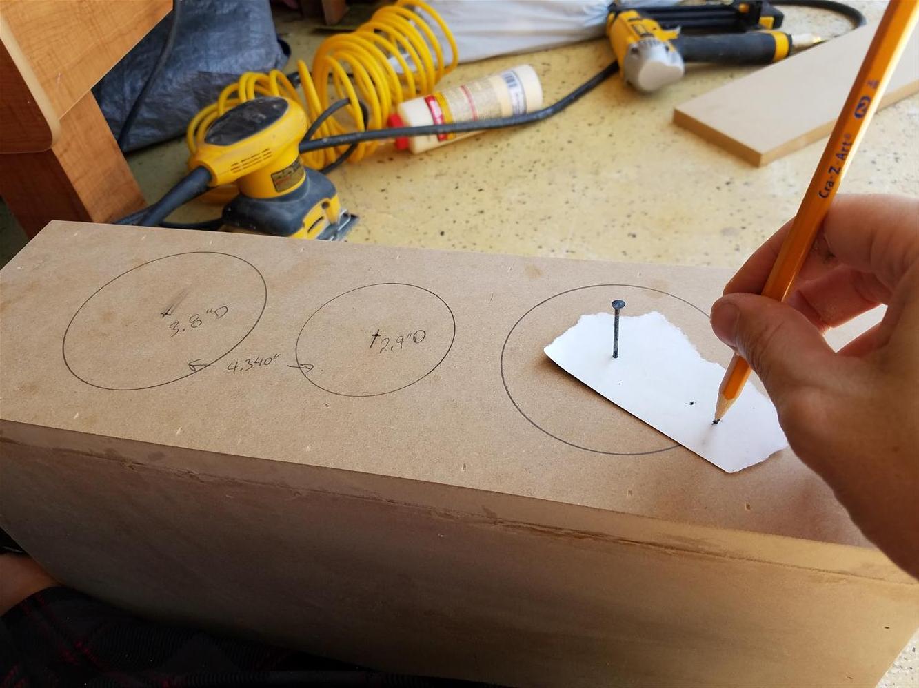
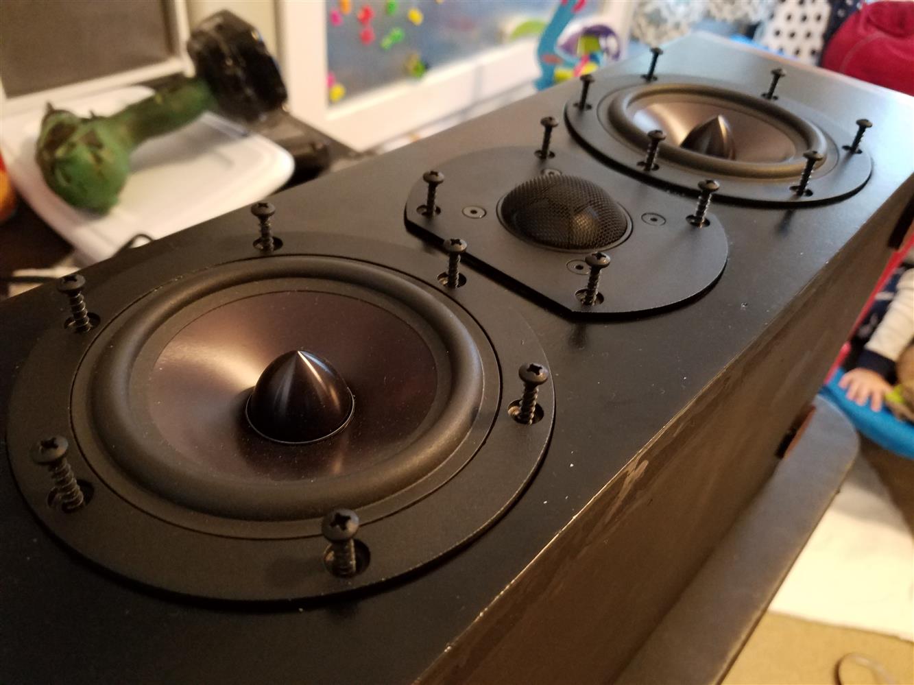 In my case I swapped out the 4.09″ standard round faceplate of the RST28F-4 for the truncated one which Parts Express used to sell for just a few dollars. This moves in the drivers by about 0.7 inches total making the center-to-center (woofer to tweeter) spacing only 4.16 inches instead of 4.85 inches. It’s not much, and arguably modeling the difference doesn’t appear to do a whole lot except that the worst-case off-axis response occurs just a few degrees further away than with the drivers an extra inch closer to each other. Ultimately that results in any given seat off dead center having just about 2-3 dB less cancellation and therefore that much closer to a flatter response. Also, I had calculated that the worst-case seat in my family room is only 30 degrees off-axis, so my target was to maximize performance only out to at most 30 degrees off axis. No sense trying to get flat off-axis response out to 45 degrees or more when nobody is going to be sitting that far to the side anyway. Especially if achieving that performance meant mounting my TV higher, spending more money, adding more drivers, making the crossover more complex or making the enclosure significantly larger.
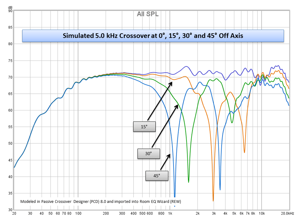
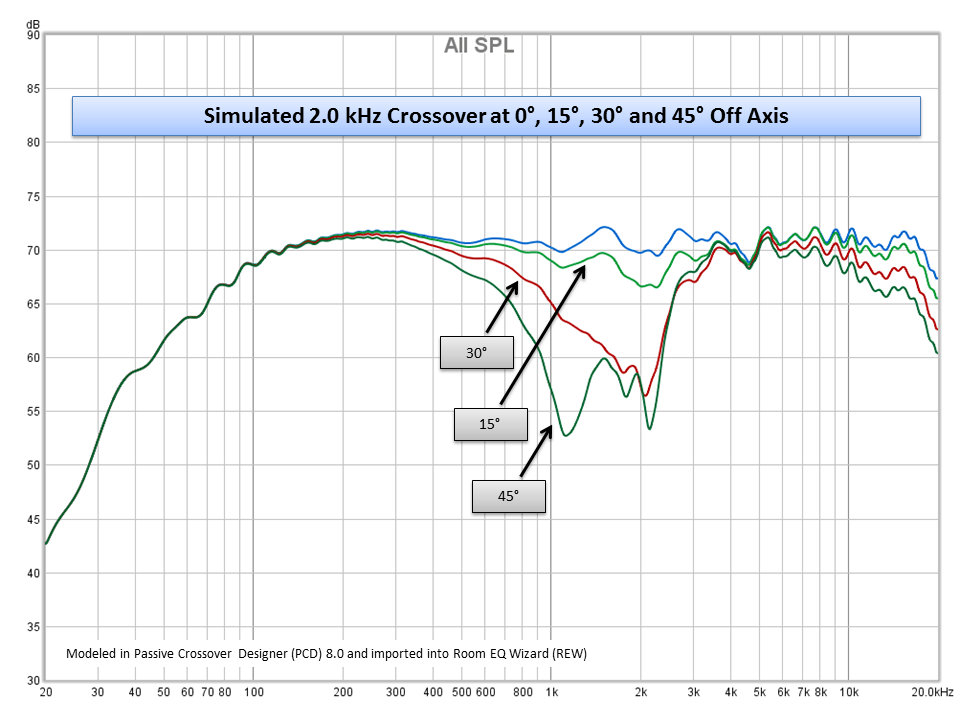
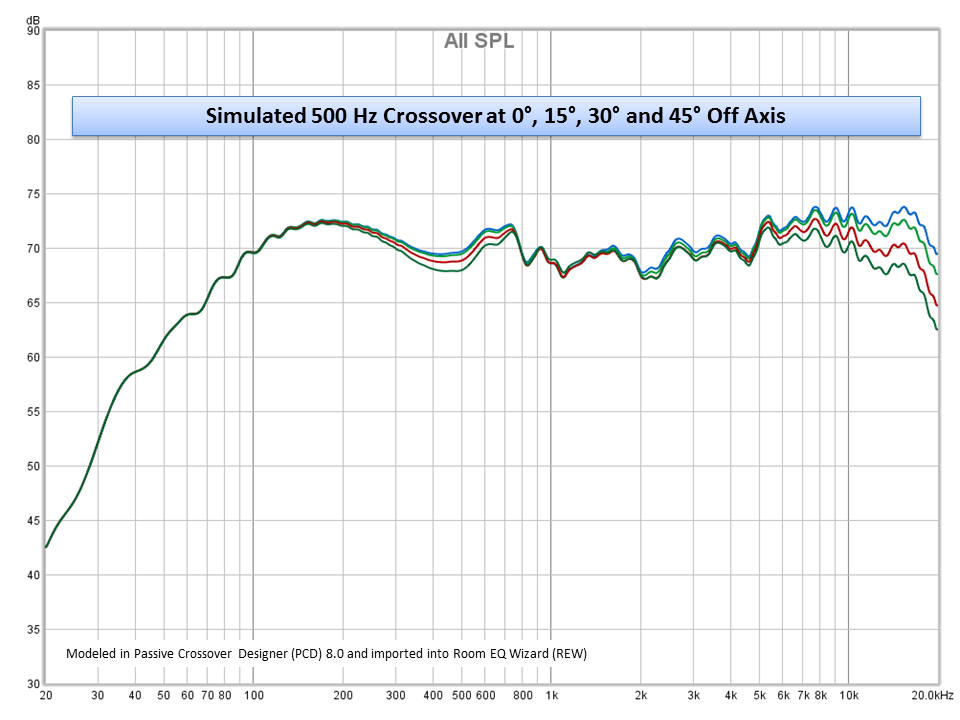
 So moving away from the layout of the drivers, the next most important thing behind the layout is the crossover design. Choosing the right crossover frequency and crossover slopes (topology) will also affect off-axis performance. I didn’t model every possible crossover combination for every possible layout configuration, so I can’t speak to all the various performance differences you can achieve, as thy are far and wide, but I did take my MTM design and ran several possible crossover designs to see which ones had decent off-axis response, even if the layout alone was the major component in crippling its response overall. I did play around with a 2.5-way for a bit, but ultimately just ended up with a standard 2-way because the crossover was simpler, cheaper and I believe I achieved an overall better on-axis response. What I could tell from the simulations was that if you decide to go with this driver configuration, the lower the crossover frequency you can muster the better. Take a look at the plots for a 5 kHz crossover at 0, 15, 30 and 45 degrees off-axis, even at 15 degrees the response is already suffering from massive comb filtering with some pretty deep nulls. And it doesn’t get any better as the listening position moves off the center line with the nulls staying in the 60 dB region and only shifting in frequency. Now let’s try modeling a semi-decent 2 kHz crossover at the same offsets. The response is still decent out to about 15 degrees, but past that we start to see more significant suckouts in the response though not nearly as deep and still quite reasonable. And then, just for fun, I attempted a crazy-low crossover point of only 500 Hz. It looks a little ugly on-axis, and is not exactly achievable in practice with this tweeter (or most tweeters for that matter) but does showcase the benefit of a lower crossover point. The response between 0 degrees and 45 degrees off axis is basically identical. Which is why a 3-way design with the two woofers crossed at no more than a few hundred hertz is in practice most likely the best, because the comb filtering effects are essentially nonexistent no matter how far off axis you go. Drop a midrange and tweeter in a vertical MT configuration between the two woofers and you’ve got yourself the ideal center channel, able to provide a great on an off-axis response for all your movie goers, even Grandma.
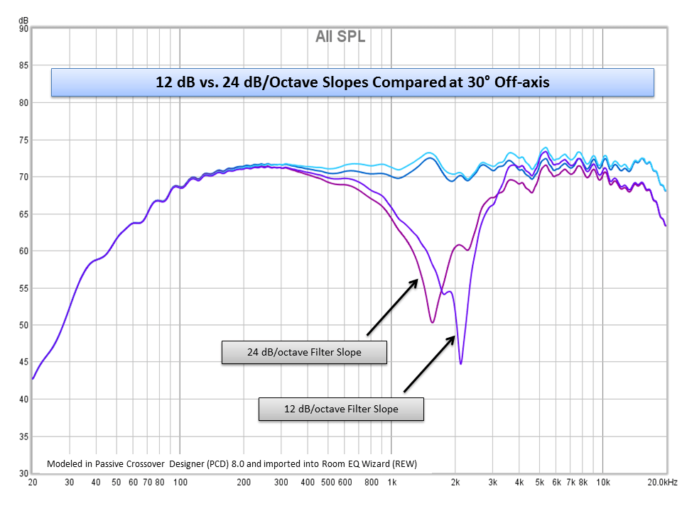
The last thing to consider is crossover topology. With standard 2-way speakers the polar response may tilt upwards or downwards due to the offset in distance between the woofer and tweeter and the misalignment in time between common frequencies produced by both drivers. Higher-order crossover slopes can help minimize the effects of this polar tilt because the steeper slopes reduce the number of frequencies that overlap across the two drivers. However in the case of a horizontal MTM, in my experience, the crossover slope plays less of a role in polarization because the two drivers are by design producing the same frequencies even below the crossover cutoff point. So while the crossover point will also begin to want to shift the polar response of the speaker either left or right as it sums with the tweeter (or in the case of an MTM, it simply focuses the sound waves into a narrower beam) the dominate lobing effect will be from the two woofers operating at the same frequencies within the filter’s passband and being spaced apart from each other. For this reason I didn’t attempt to shoot for exotic crossover slopes and kept them to simple 2nd order 12 dB slopes. However, two reasons to go with higher-order slopes would be for tweeter protection or to reduce cone break-up modes of the woofers. You can see here where I modeled both a 12 dB/octave filter against a 24 dB/octave filter and at 30 degrees off axis, either response suffers from comb filtering creating decent suckouts in the response. While they are slightly different, neither are really better than the other in my opinion. But your experience may vary. I didn’t spend a lot of time analyzing, building and measuring a lot of different topologies, so fundamentally it’s not unreasonable to expect that the topology does play a role in comb filtering effects in both the horizontal and vertical dimensions because you effectively have another driver (the tweeter) also producing frequencies spaced out of alignment with the woofers which will in effect cause lobing when seated off-axis in any direction.
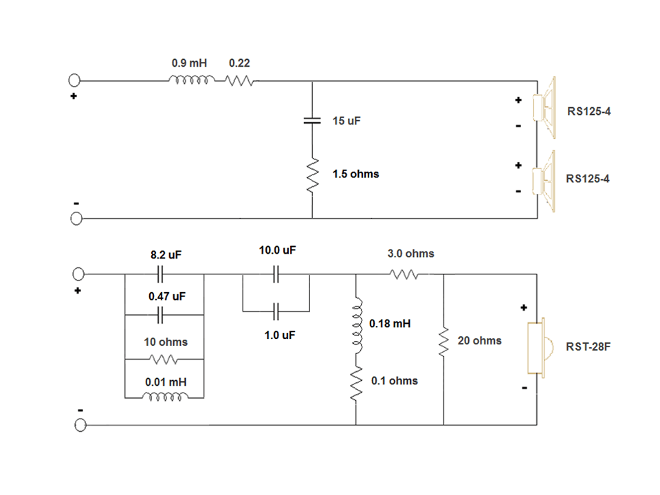
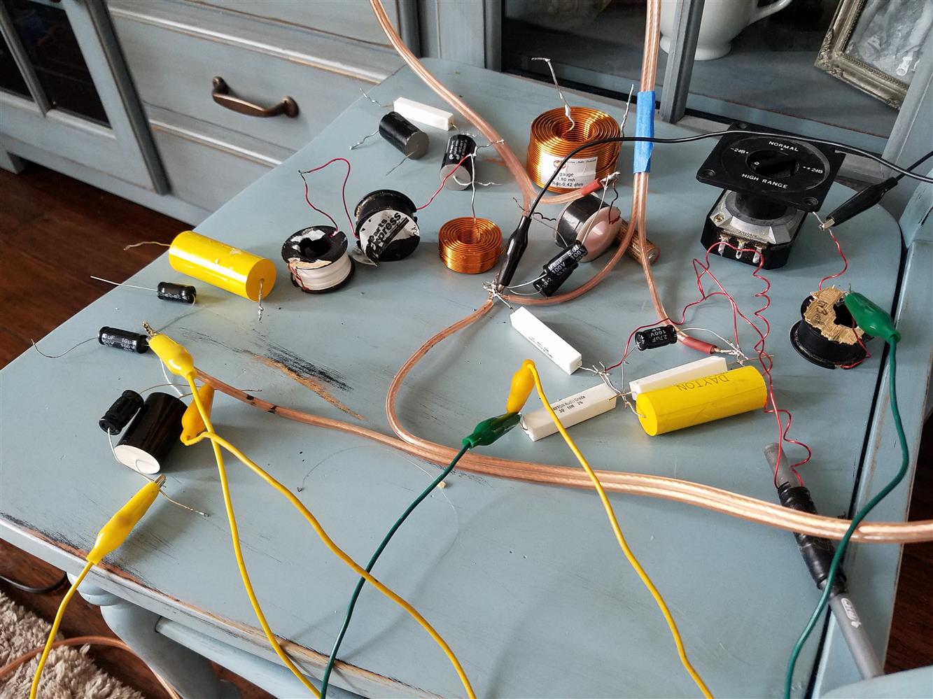
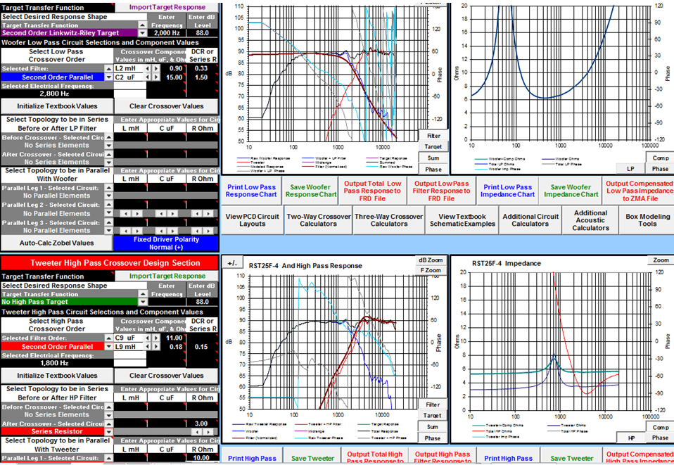
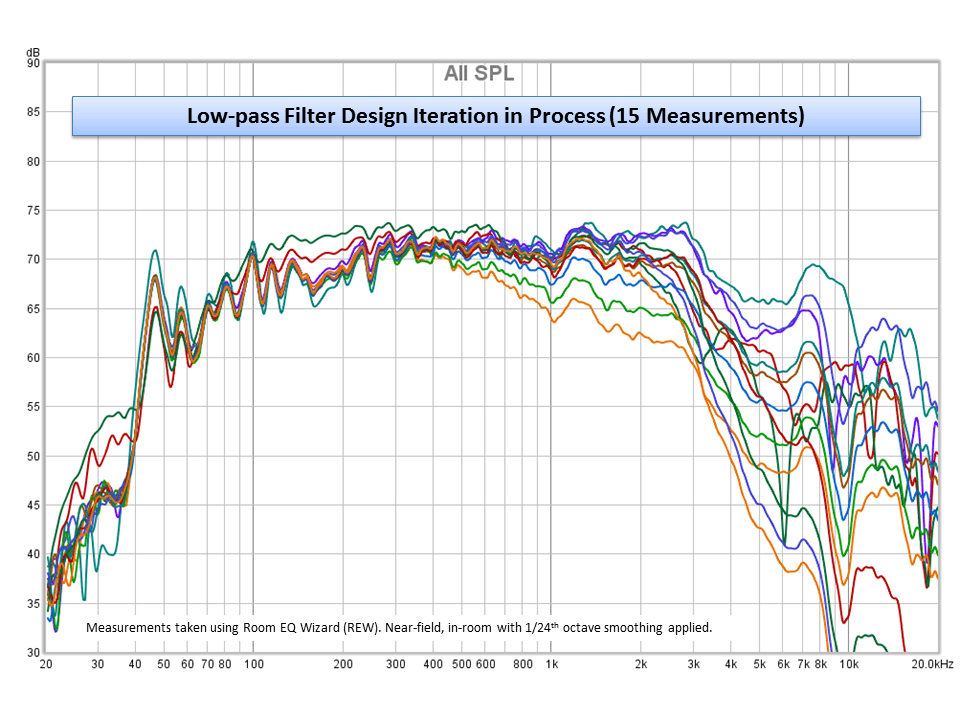
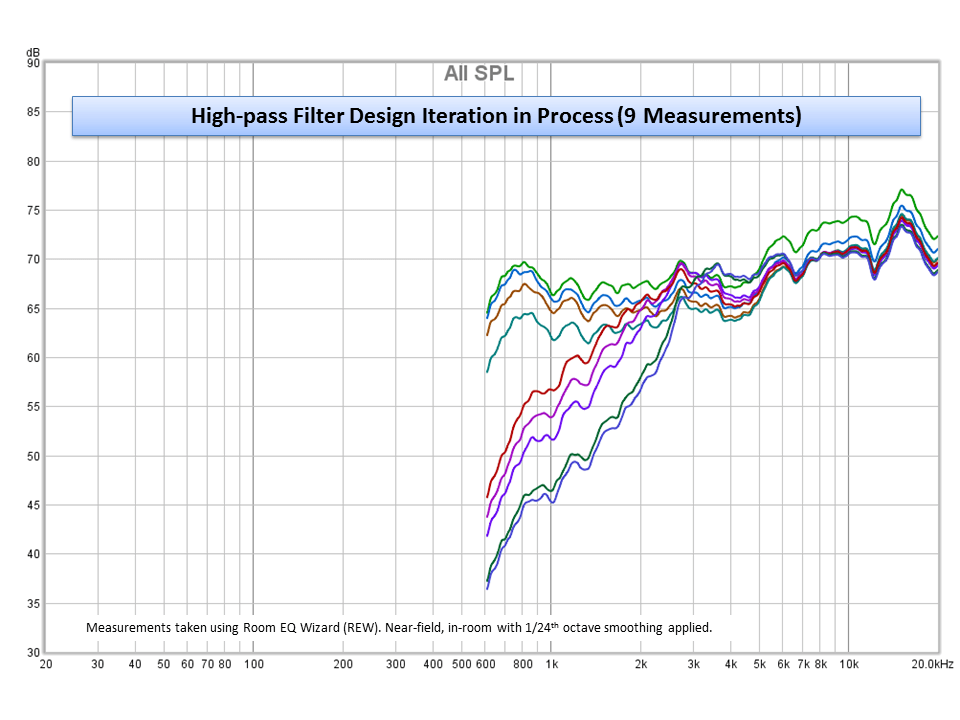
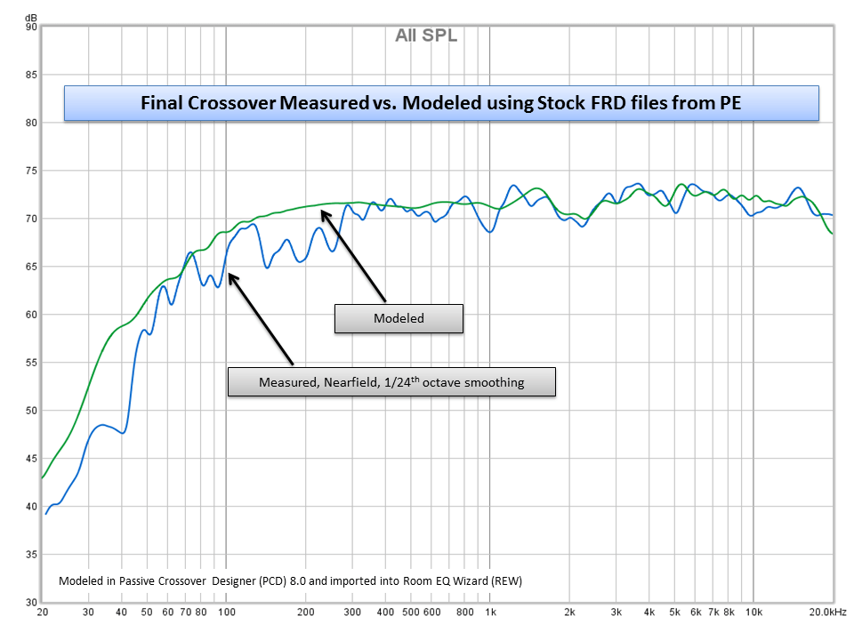
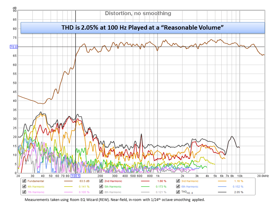
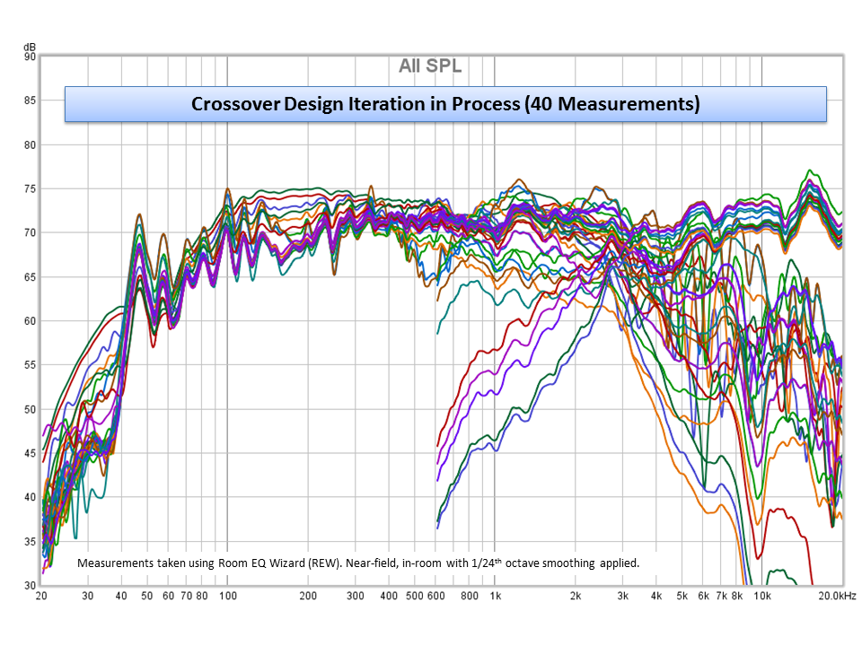 Anyway, I’ve rattled on and haven’t really even began to describe some of the other elements of this speaker design. I simulated the initial crossover in PCD just to get an idea of where to start and then built up a breadboard version of the crossover and then started tweaking. I spent a couple of weeks with Room EQ Wizard (REW) and my ECM8000 microphone measuring mainly the on-axis response of many different crossover options. I stuck with basic 2nd-order slopes for simplicity and as described previously. Cone break-up modes were well suppressed in the final design and no notch filtering was required. The Dayton RST28F-4 can easily handle 2.7 kHz at 12 dB/octave and showed no signs of fatigue. Distortion plots are shown here for reference as well. For the woofers I played around with inductors values as small as 0.3 mHz and as large as 1.8 mH and cap values from 4.7 uF all the way up to 25 uF. I settled on 0.9 mH and 15 uF as it provided the flattest on-axis response, summed nicely with the tweeter and suppressed cone break-up modes enough to be acceptable. See the plots below which show the difference between 12, 18 and 24 dB slopes. Cone break-up modes are suppressed about 30 dB with a 2nd order slope, a 3rd order slope buys you another 10 dB and a 4th order slope reduces the break-up modes to better than 50 dB. You could do better, but with limited parts I had on hand, this is basically what I came up with. With minimum parts count, this crossover is inexpensive and still does its job nicely. Not to mention the RS125-4’s don’t have terribly peaky cone break-up modes and is fairly easy to tame. I could have thrown in a quick notch filter (a single cap in parallel with the inductor) to suppress that peak at around 7 kHz, but notch filters are pretty narrow band and in this case would have likely provided little benefit. In the end I added a 1.5 ohm resistor in series with the 15 uF capacitor to reduce some peaking just before the filter cutoff. This effectively alters the Q of the filter, making it more damped, which helped flatten out the corner which resulted in a slightly flatter frequency response around the crossover frequency. This further sacrifices a few dB on the rejection side of things, but not so much to be noticeable and I liked the benefit I got from the flatter in-band response.
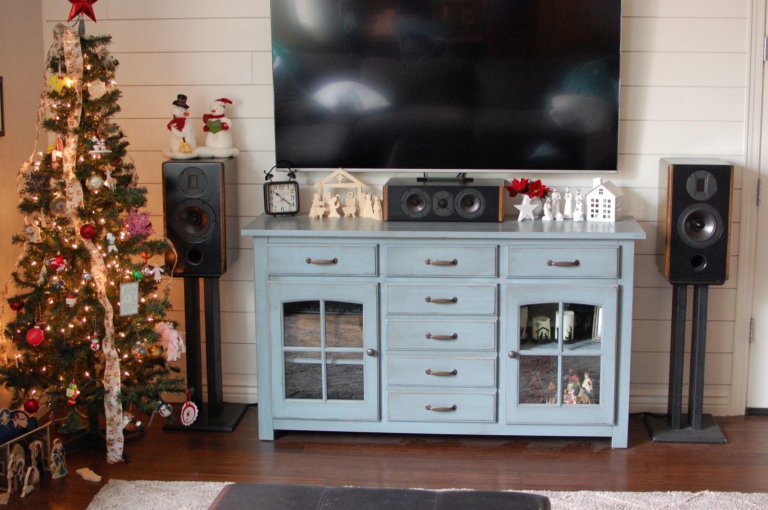
The tweeter is a basic 12 dB/octave as well. I’m not sure if these come out to be Butterworth or Linkwitz-Riley filter types or something else. I basically just tweaked with the cap value and inductor value until I got something I liked. They are far from textbook and match pretty closely to the predicted values from Jeff Bagby’s PCD. PCD got me started and then from there I measured and tweaked until I found something that looked reasonable. I probably took on the order of 200 measurements of this speaker with various combinations of crossover values. The final design basically attempts to achieve the flattest overall frequency response at 18 inches from the speaker with the speaker in the center of my room. Room modes are certainly taking effect and I did nothing to account for baffle losses. Since this is a center channel speaker, it is going to be placed right up against the wall underneath my TV and on top of my media console. So any amount of BSC seemed unnecessary and would have likely resulted in a boomy bottom end with lack luster mids and highs. I did add a little notch filter no the tweeter because the Dayton RST28F-4 has a bit of a peak at about 15 kHz. It doesn’t show up in Parts Express’s measurements, but was very obvious in my measurements. It matched quite closely to the peak in the Hi-Vi RT1.3WE tweeters as well. I had tamed those with a simple series RCL network, so I did the same on the tweeter here. In the end I was shooting for an overall flat response on-axis but also was attempting to match the timbre of my main speakers, the RTS181.3 bookshelf speakers. I pulled up the final frequency response plots in REW for those speakers and compared them to my center channel. Things were looking good! I balanced the tweeter level by adjusting the series/shut resistors (L-pad) until the two response almost lined right up. So while even though I don’t have the same woofers or tweeters in my front three speakers (LCR) I’ve got them “timbre matched” about as best as I possibly can do. Other than the left/rights having more bass, they sound very nicely matched. And that’s about all I can hope for.
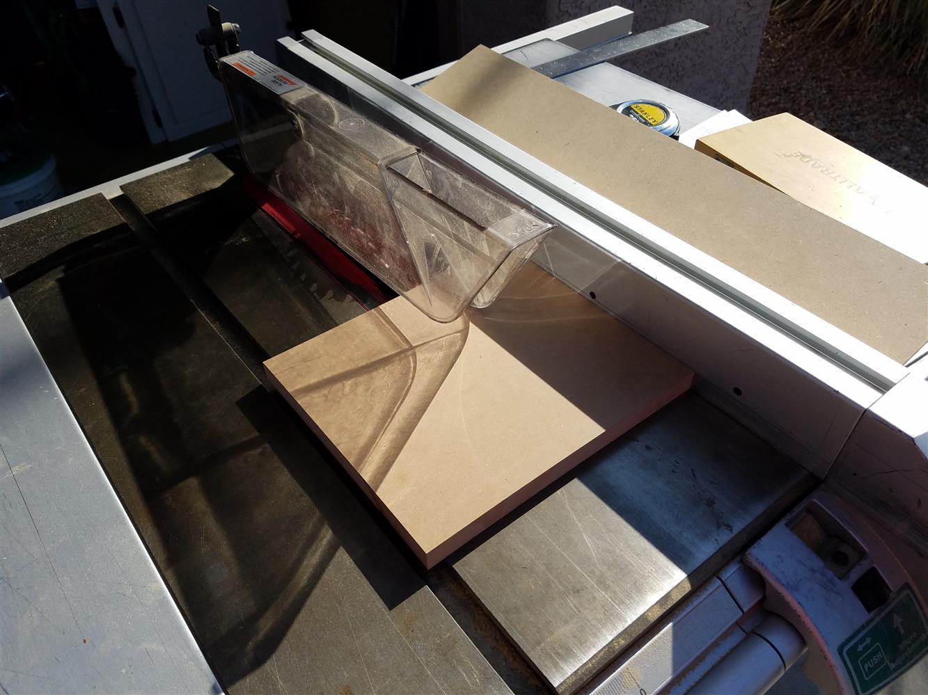
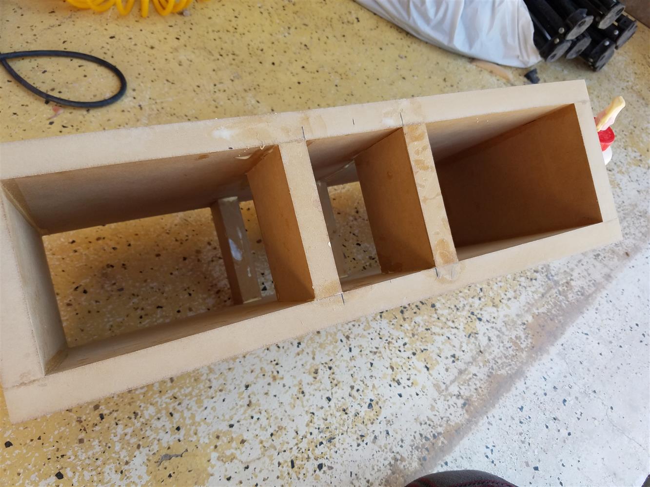
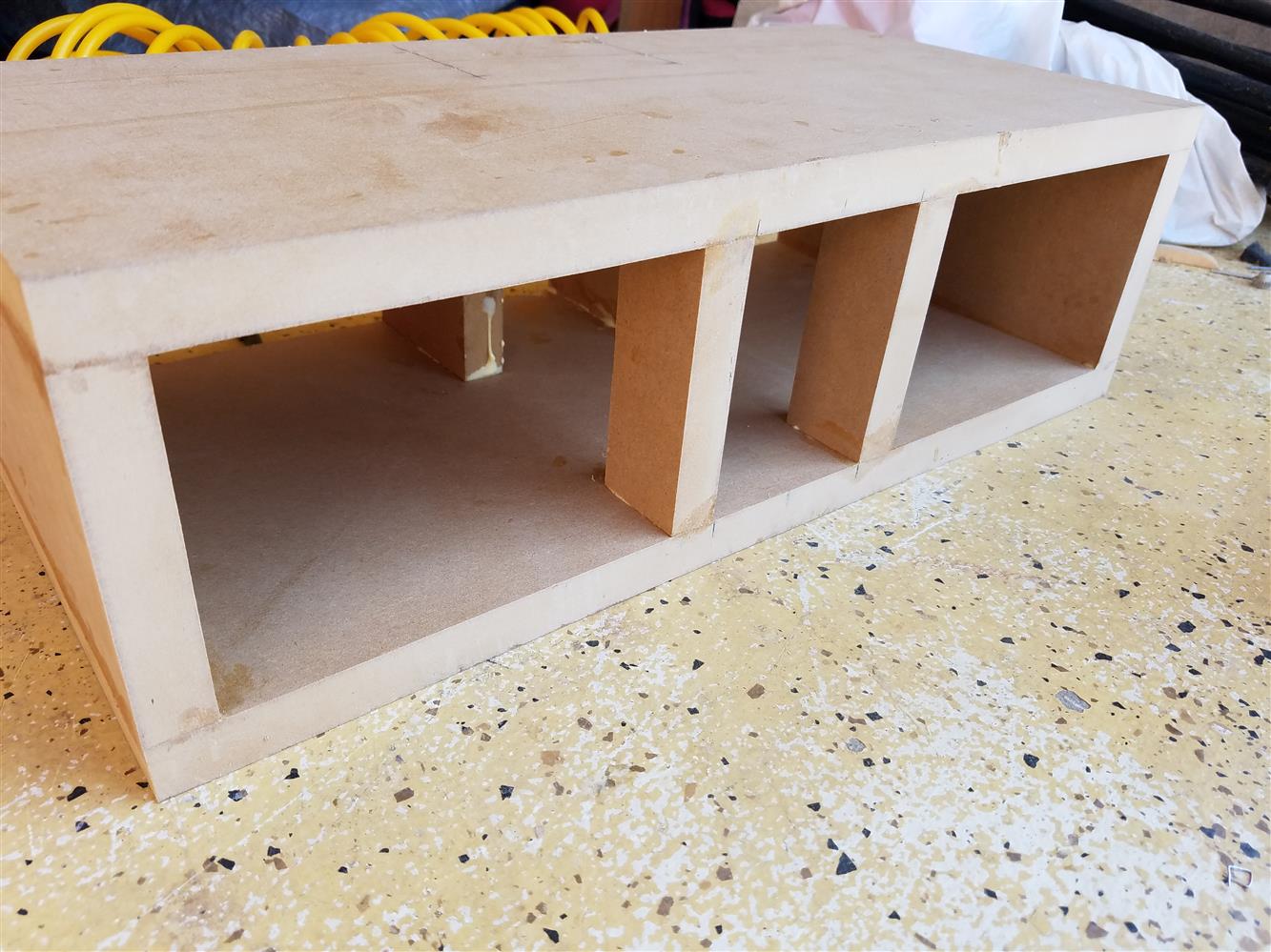
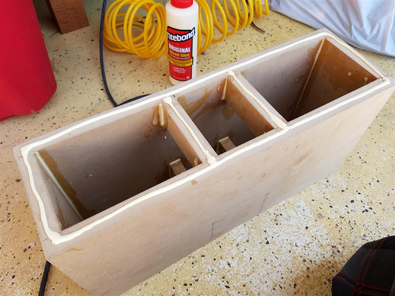
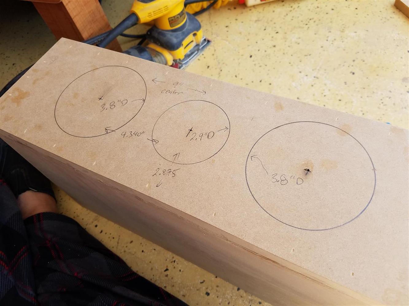
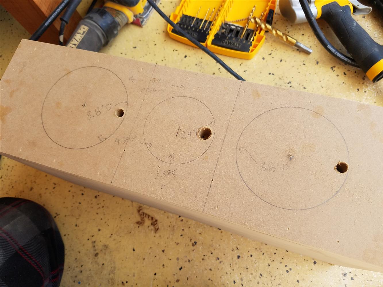
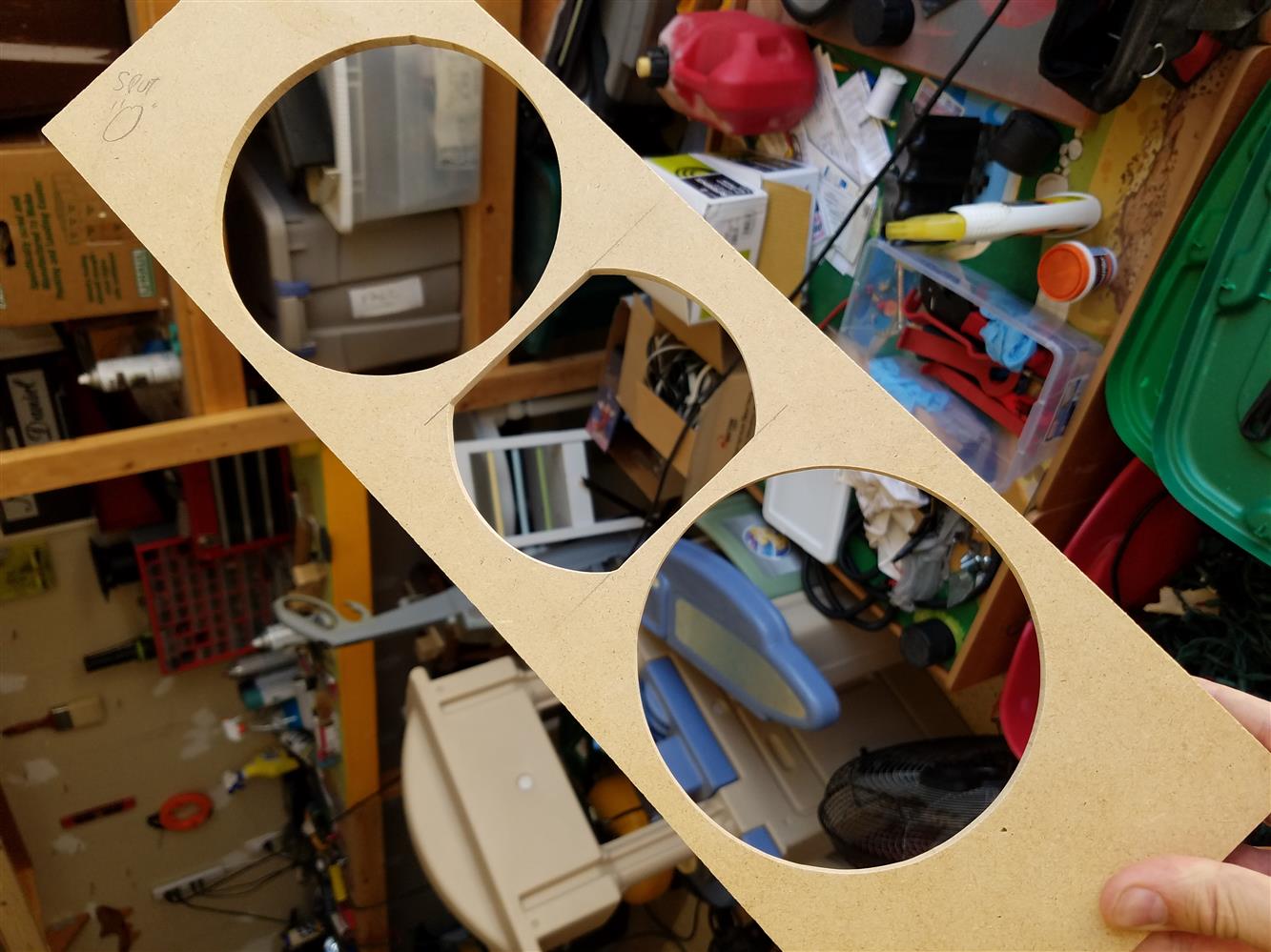
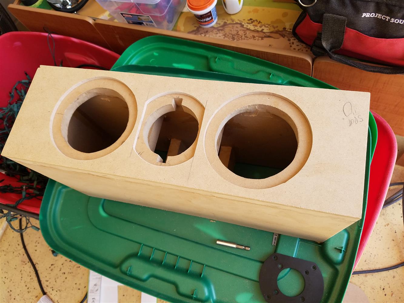
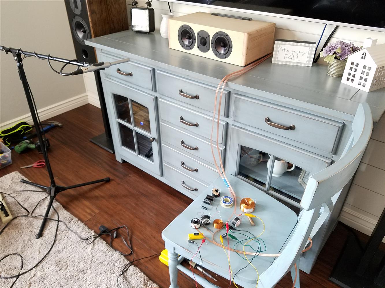
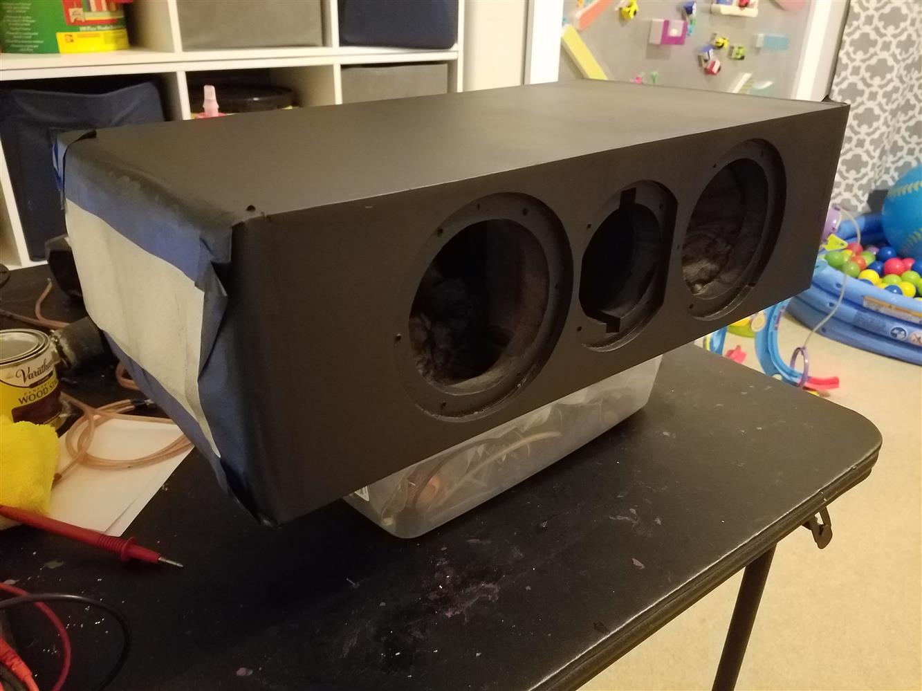
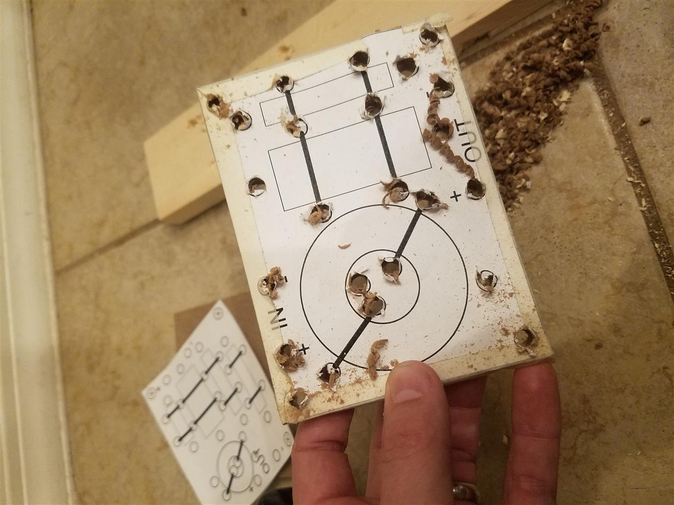
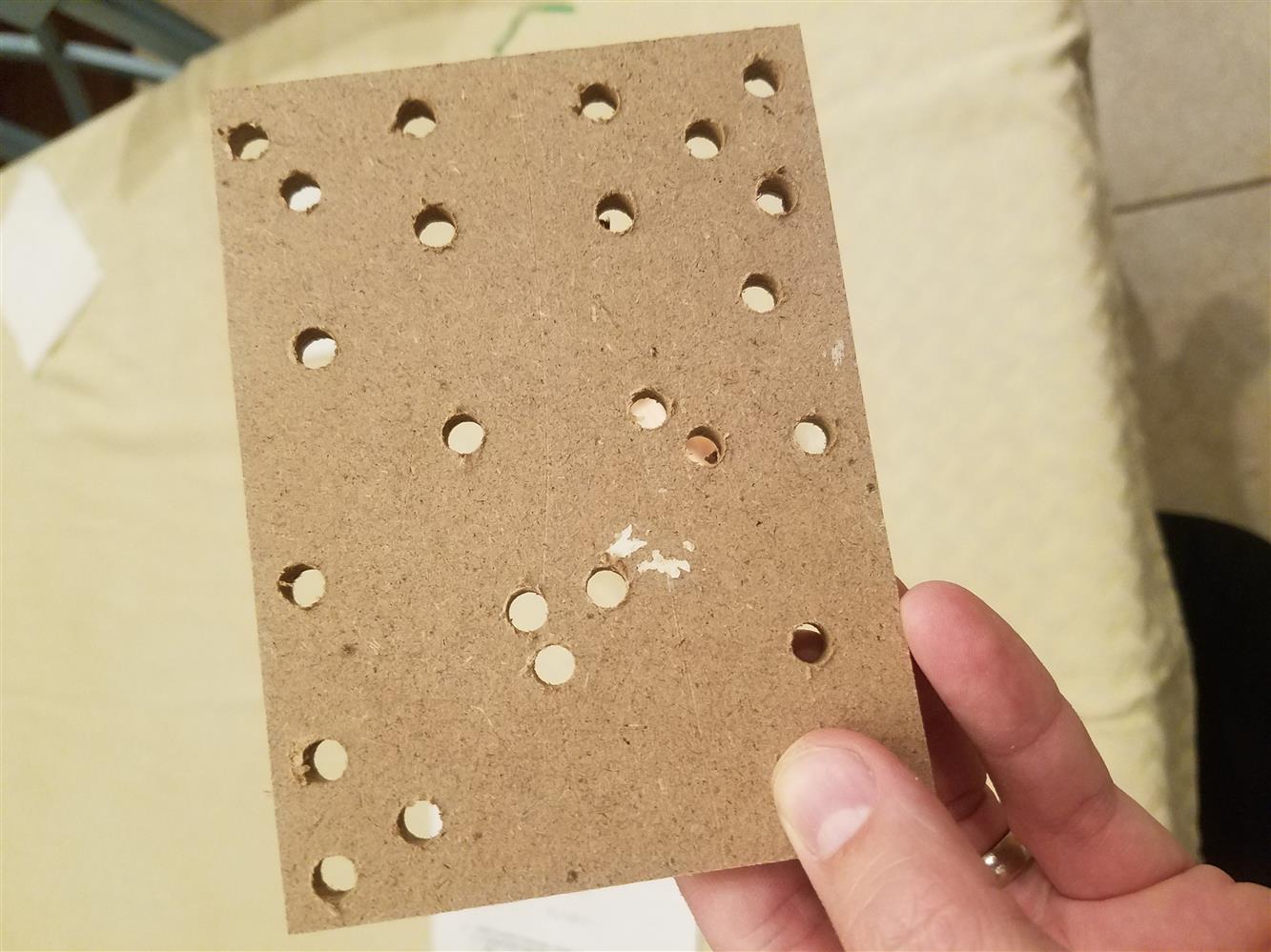
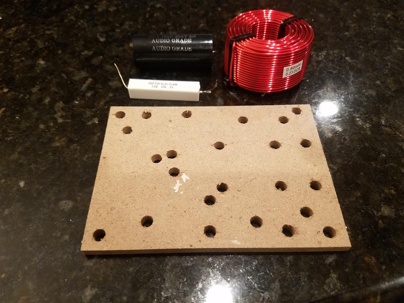
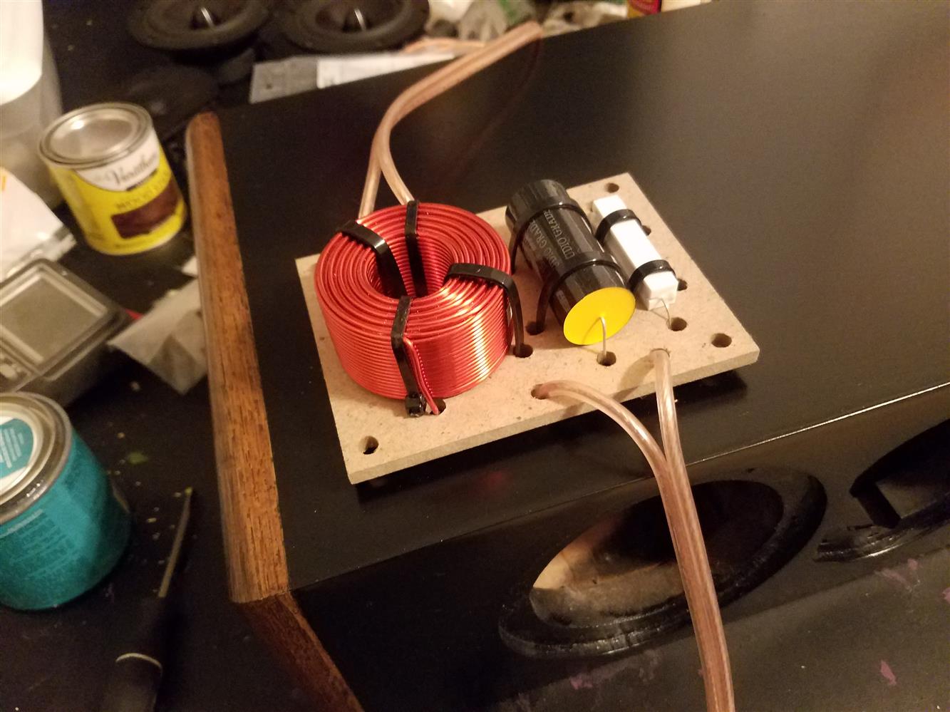
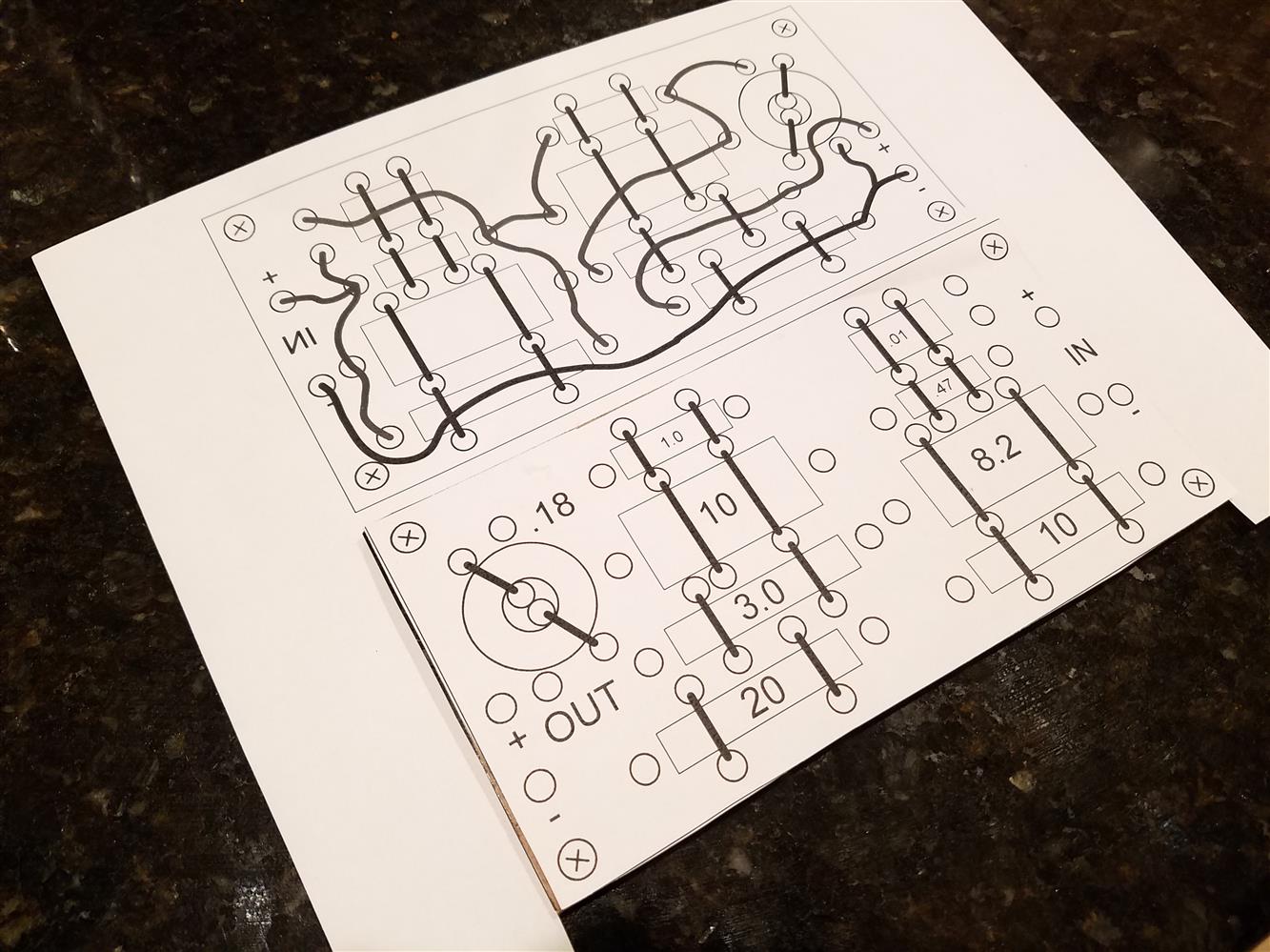
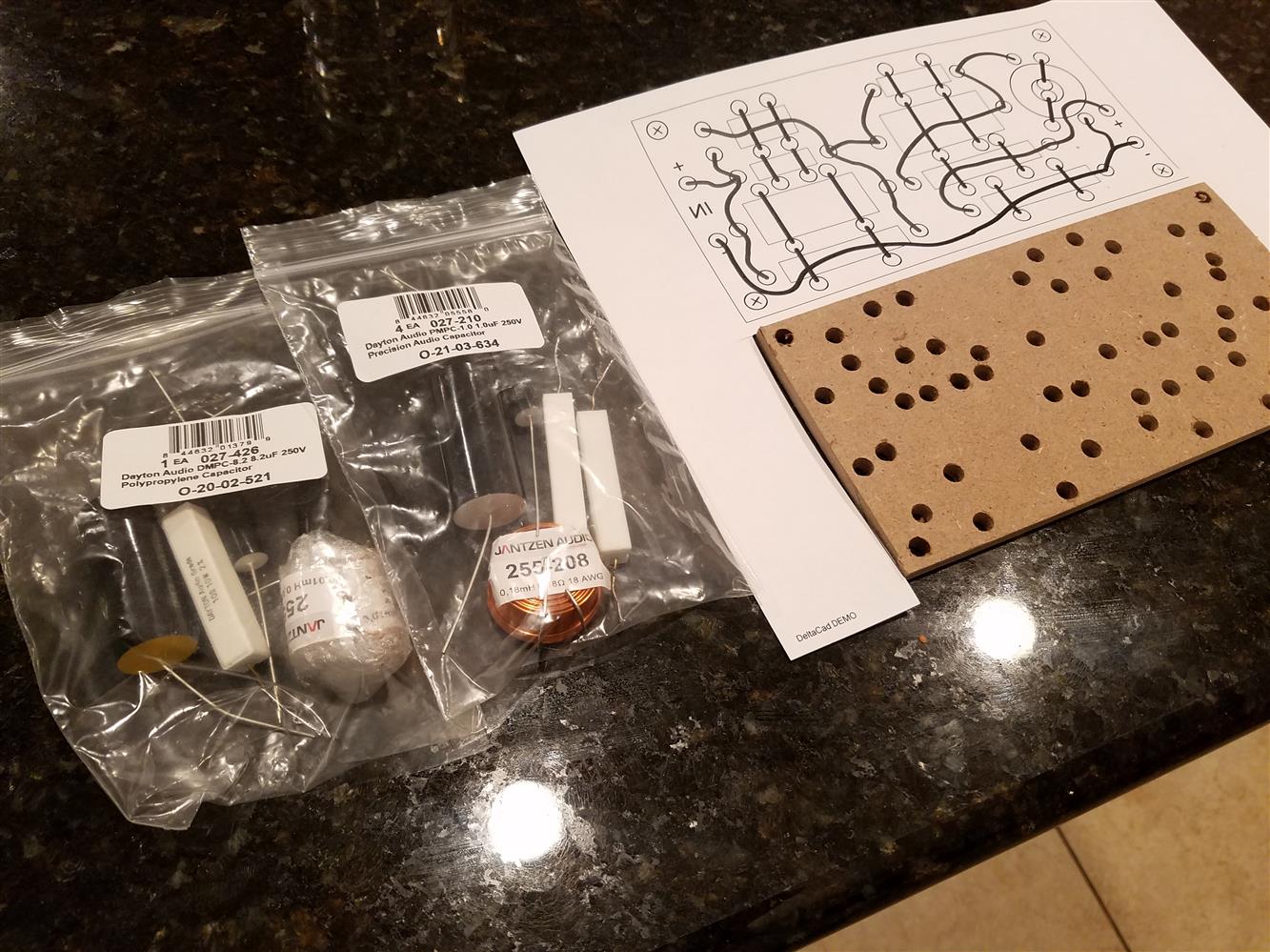
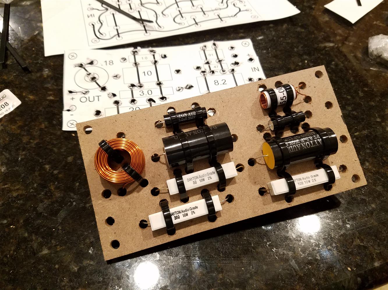
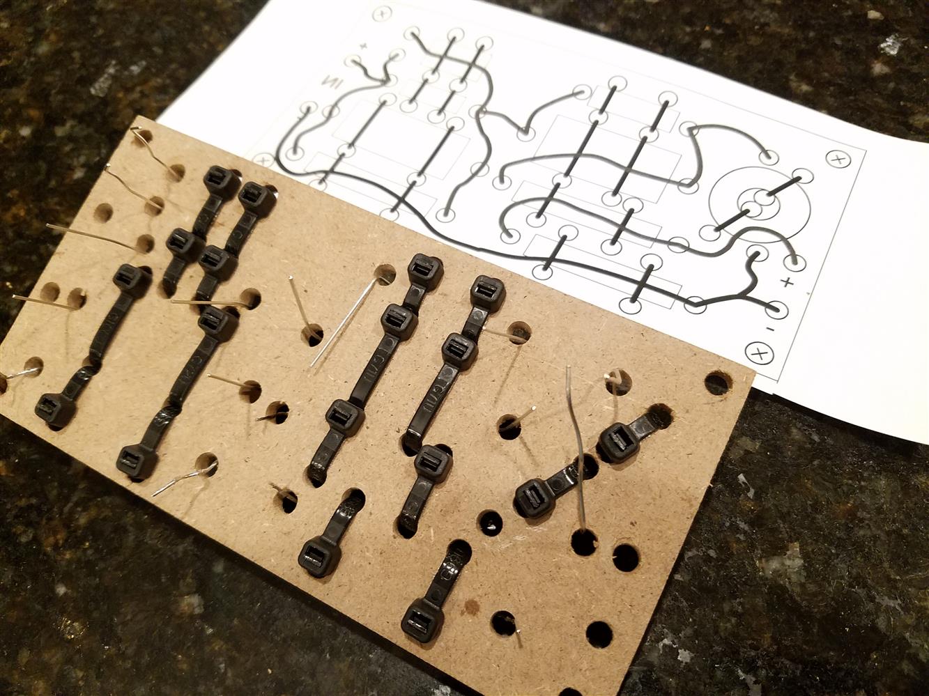
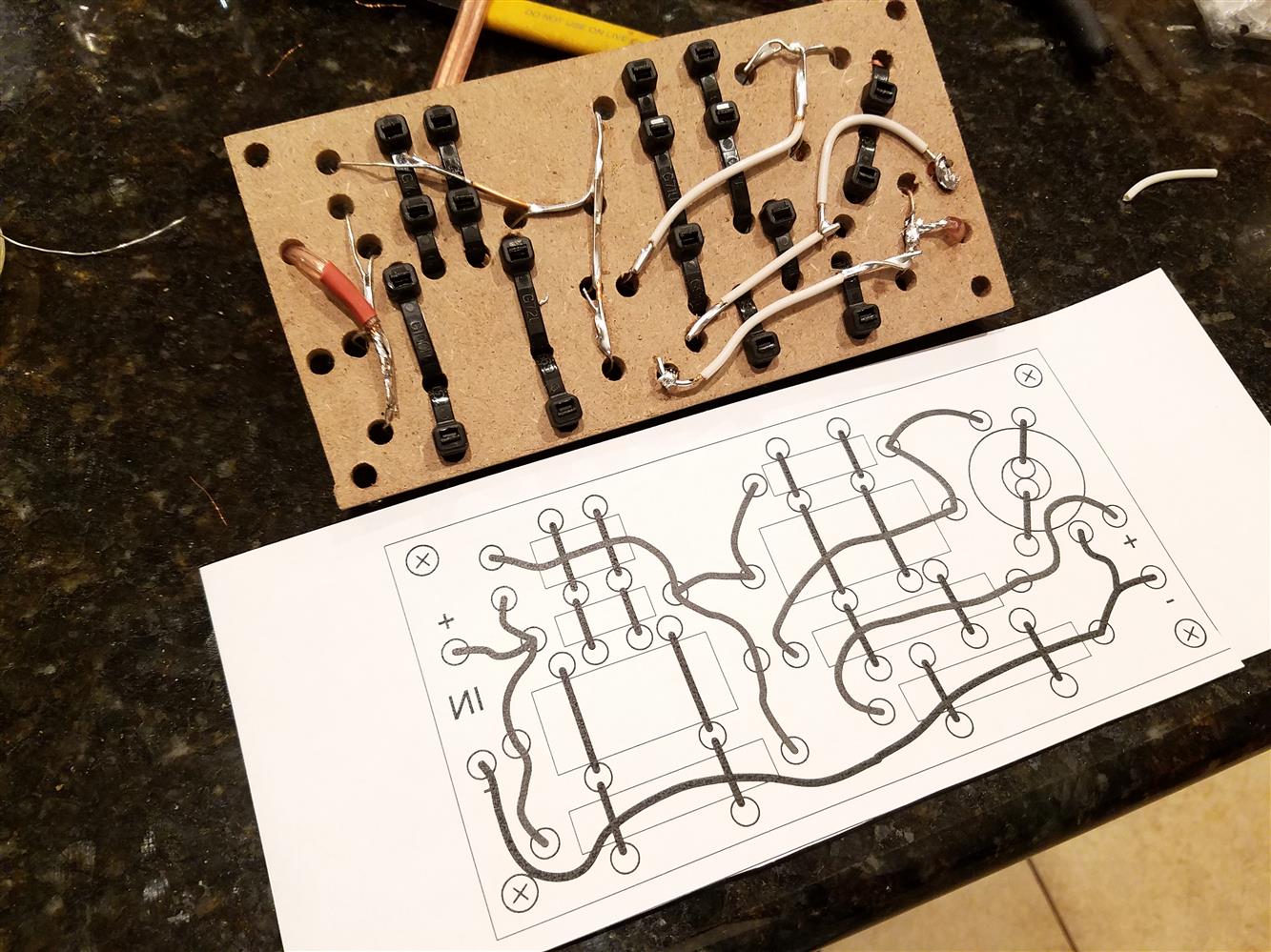
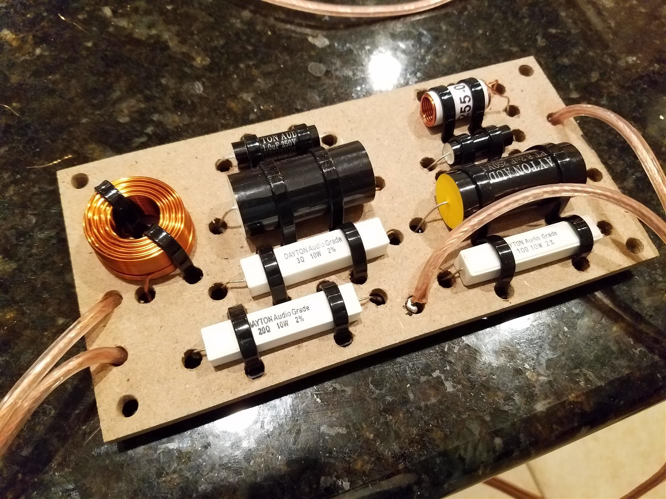
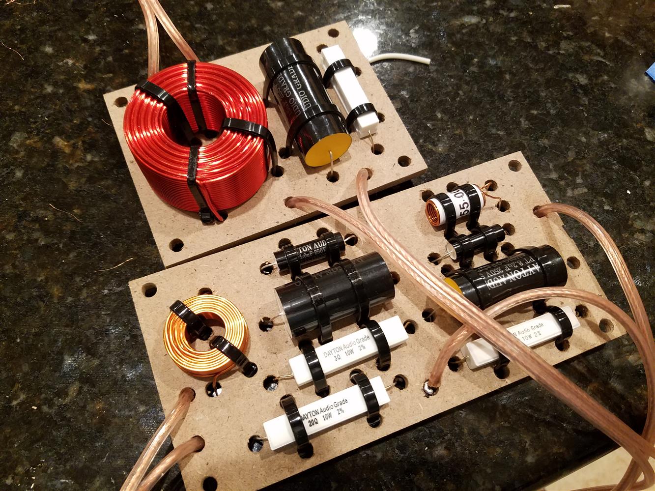
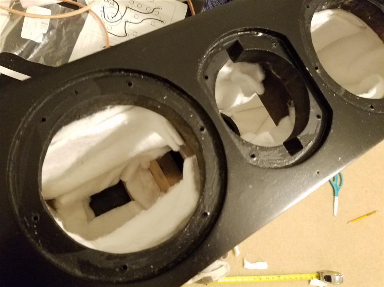
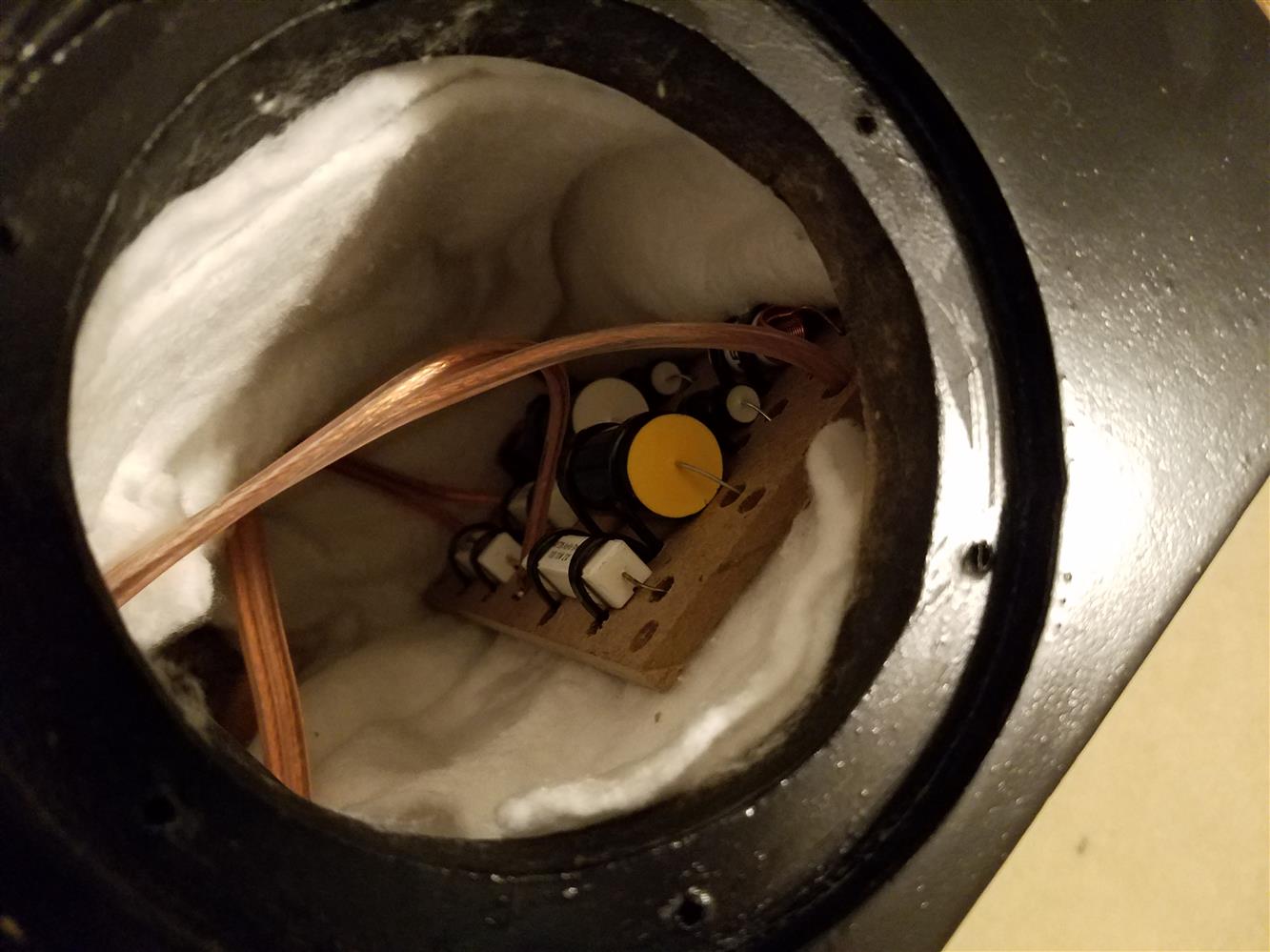
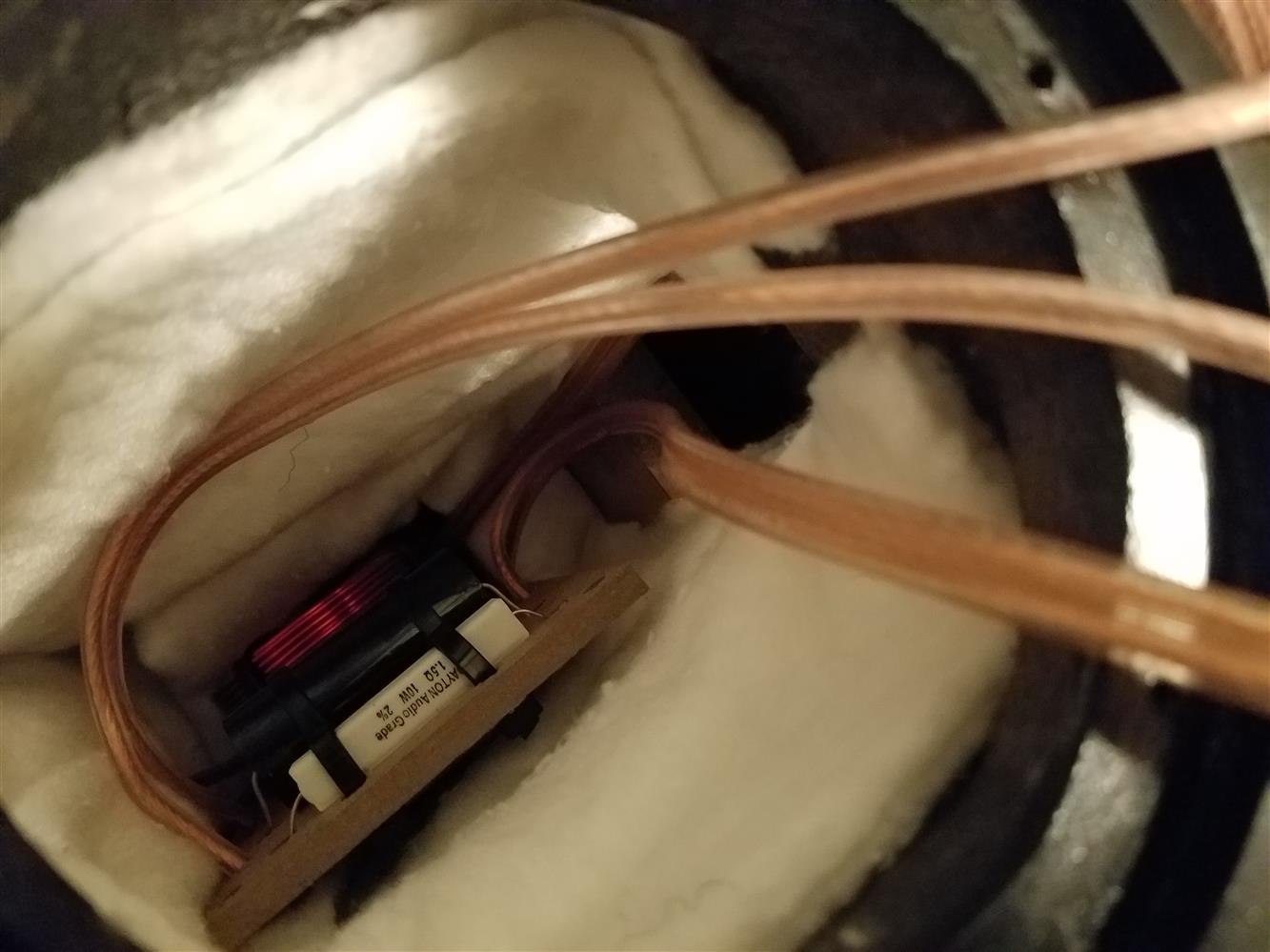
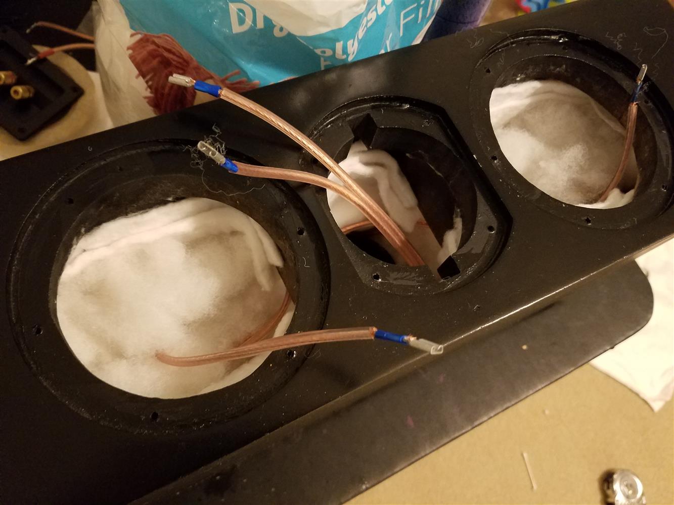
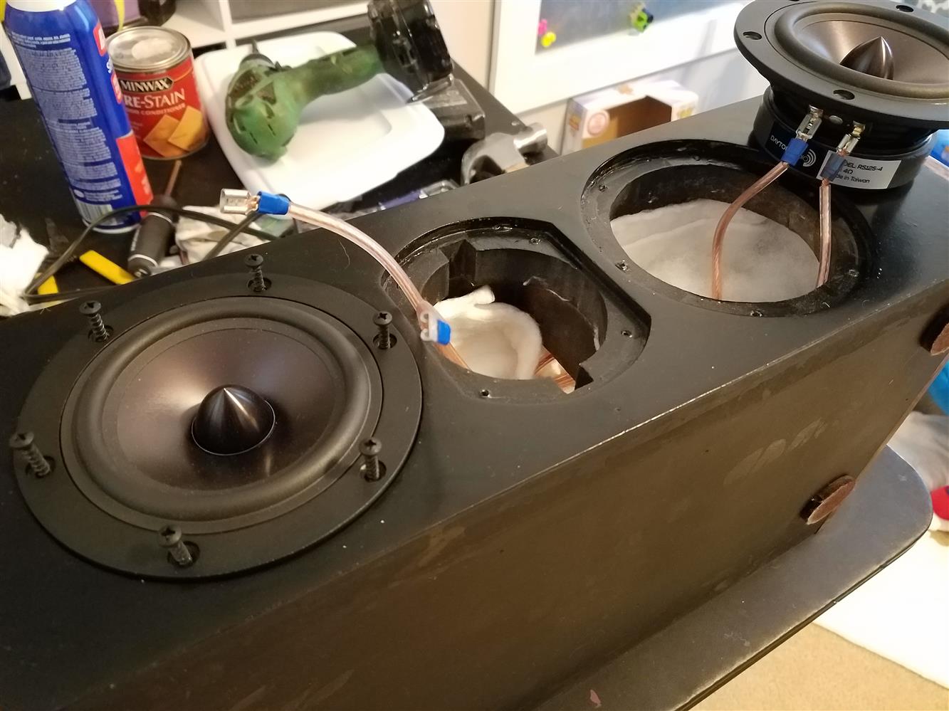
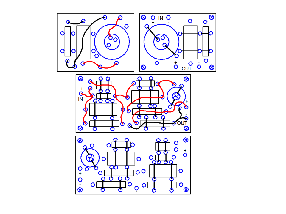
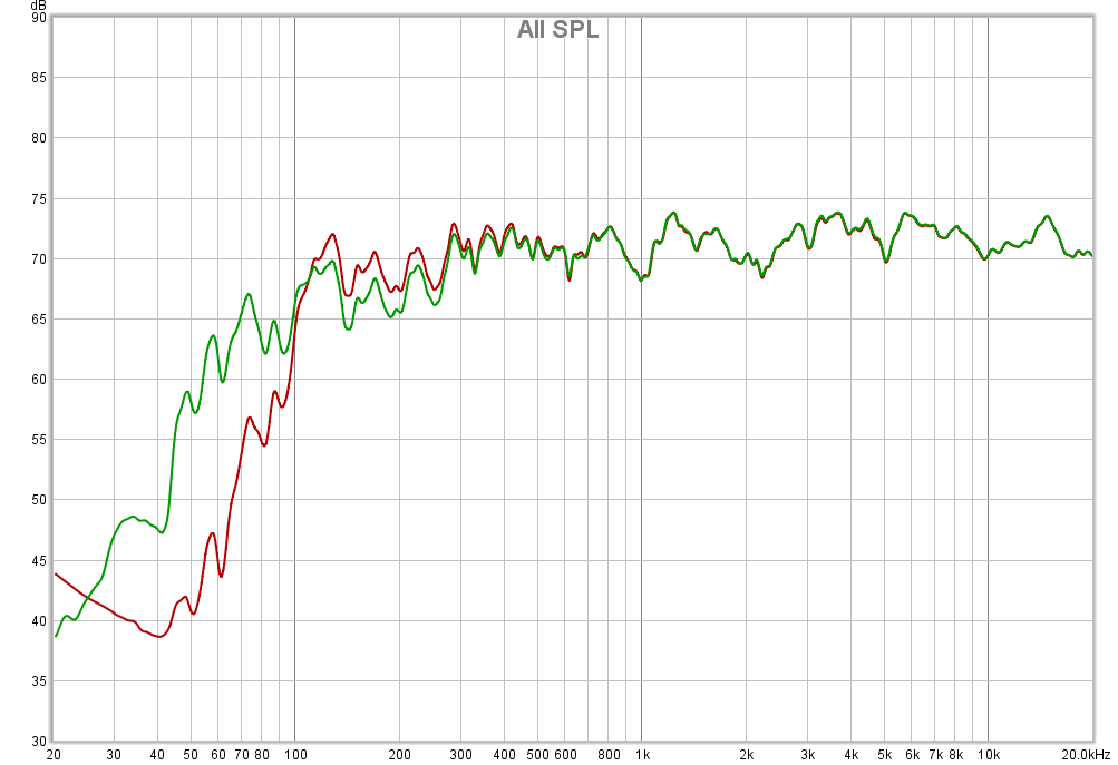
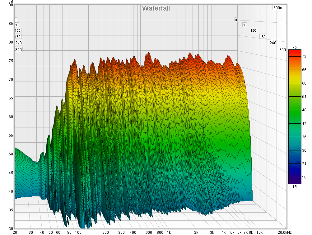 Alright so after weeks of playing around in REW with the crossover, I settled on the final design, I went ahead and added to my cart the actual values of everything I needed at Parts Express, placed my order and said to myself, okay, now I’m committed! Parts arrived later that week and then began the fun process of building the crossovers and finishing this speaker project once and for all. Also, I painted and stained the speaker while I was waiting for the parts to arrive. Check out the pictures below. I drew up a crossover layout in DeltaCAD, printed them out and then drilled holes for the zip-ties and part leads. I mounted the parts and basically did point to point soldering for everything on the backside of the board. I separated the woofer and tweeter boards because otherwise the crossover was too big to fit into the little 4 inch woofer holes and then into the speaker box. So the woofer crossover is on one board and placed in one side of the cabinet and the tweeter is on another board and placed on the other side. Everything fit nicely in the end. I added some cotton batting to the walls with some spray glue and then filled about 50% the cabinet with polyfil stuffing. Internal cabinet damping or stuffing is super important in a center channel and should not be overlooked. This is critical to minimizing internal reflections to help keep dialogue and voices sounding clear and natural. See the waterfall plots shown here which give some idea of the overall response decay of the speaker. For the most part, all frequencies are falling at about the same rate and there are no obvious frequencies that ring, resonate or have an overly extended decay. I haven’t done a lot of comparisons of waterfall plots though and I didn’t measure the speakers with no fill just to compare them. But I have noticed in speakers gone past that with less stuffing vocals sounded more hollow which also makes dialogue less intelligible. Anyway, you have to play around with types of stuffing materials and quantity of stuffing until you find something that works and sounds best to your ears. For small speakers like this, I’ve found that more stuffing tends to be better as it reduces response peaks making the speaker sound flatter and improves the decay response making the speakers sound less hollow. Bass begins to suffer as the stuffing gets to be too much, so you just have to find a balance.
So with all that I will leave you with a plethora of build pictures, measured response plots, enclosure modeled plots, crossover modeled plots and final pictures for you to peruse at your leisure. Which brings me to my final conclusion that this speaker sounds amazing from all seated positions. Dialogue sounds rich and clear, is totally intelligible and tonally doesn’t sound as different in the corner seats as the individual plots would seem to elude. So don’t fret Grandma, you’ll be able to hear the movie just fine. Which goes to show that even a horizontal MTM, if at least some critical consideration is taken to keep the drivers close together and the crossover over frequency as low as possible, then it’s not a complete deal breaker in a home theater and can provide perfectly acceptable sound quality for a wide range of seating. And with that, thanks for stopping by and for taking the time to read my ramblings. Hopefully there’s something to learn in all of this. And if there’s something blatantly incorrect here or you disagree with something I may have written here, feel free to leave a comment below. I don’t claim to have all the answers and as with a lot of hobbies like this there’s both subjective and objective elements to speaker design. I try to stick to the stuff I know through my experience and keep my opinions as objective as possible, with data to support it, but I tend to wander and for me that’s okay, because this is just a blog, and that’s exactly what this blog is for, just to share my hobbies with the world. Enjoy!
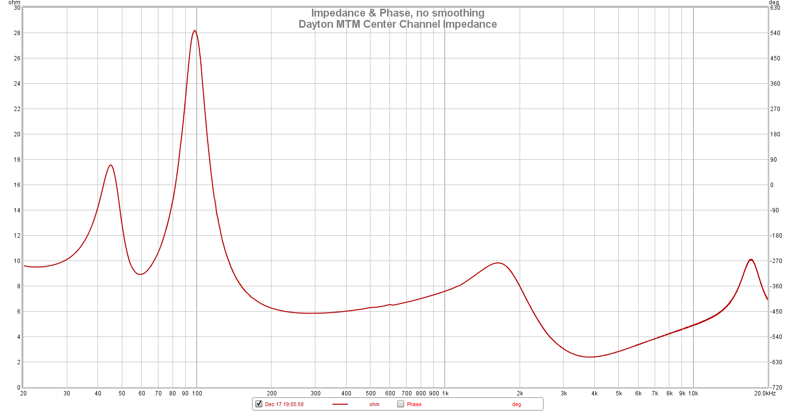 2021 Update: So this past weekend I finally got around to building an impedance jig that works with REW so I could take some impedance measurements of some of my speakers. It’s not something I’ve traditionally done, or do very often, and for a while I thought one channel on my soundcard wasn’t working, so in effect I couldn’t take impedance measurements. Anyway, I got that all sorted out and after making the necessary cable connections across a 100 ohm resistor I was in business and able to take impedance measurements to my heart’s content. So I pulled down the Dayton MTM off the media console, hooked it up to my little jig and took this impedance measurement you see here. Oh no, look at that dip at 3-4 kHz, it’s down to 2 ohms! Whoops. Basically everything from 2.5 kHz to 8 kHs is below 4 ohms. I looked back over my schematic and played around with PCD 8.0 and realized what I did. Basically that shunt 0.18 mH inductor right after the capacitor is such a low value that it’s creating a super-low impedance to the amplifier right at the crossover point. All of the padding to get the tweeter balanced to the woofer is done post the crossover network so it does no good to bring up the impedance. Ignoring the low impedance, it models well and measures well, but I probably should have moved some of that padding to before the crossover network. If I were to do that however it would take slightly different values to get the same FR response and since I don’t really have any intentions of messing with this speaker again, I’m just going to leave it. But note to prospective designers, this design has an unusually low impedance caused by not putting a series resistor in front of the crossover network and pushing the inductance of that shunt inductor value way down to only 0.18 mH. A higher value inductor would raise that impedance, but also mess with the crossover point, which means needing to tweak all of the rest of the components. Anyway, something to keep in mind! At this point, my AVR rated at only 6 ohms minimum has never complained, or shut off or gone into thermal protect. Fortunately it’s pretty high in frequency so it’s not overly demanding. Just the same, don’t forget to take impedance plots! Also, PCD predicted this, I just ignored it like a dumb dumb.
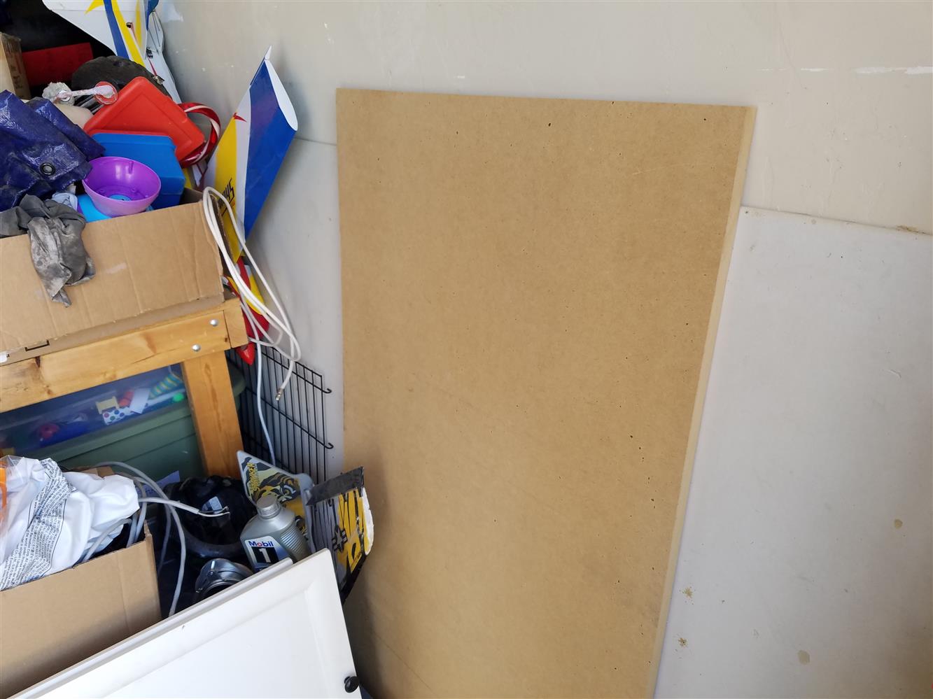
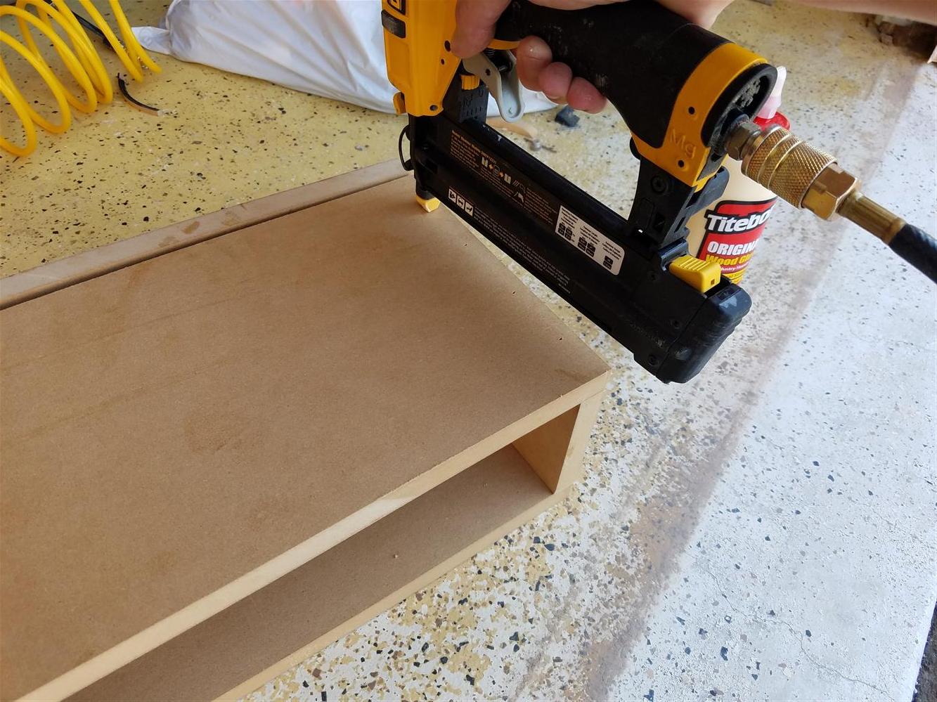
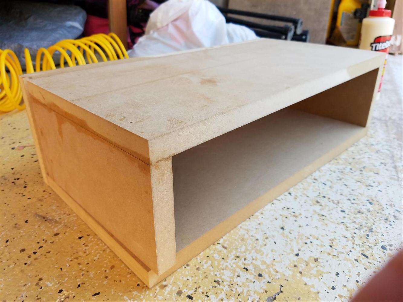
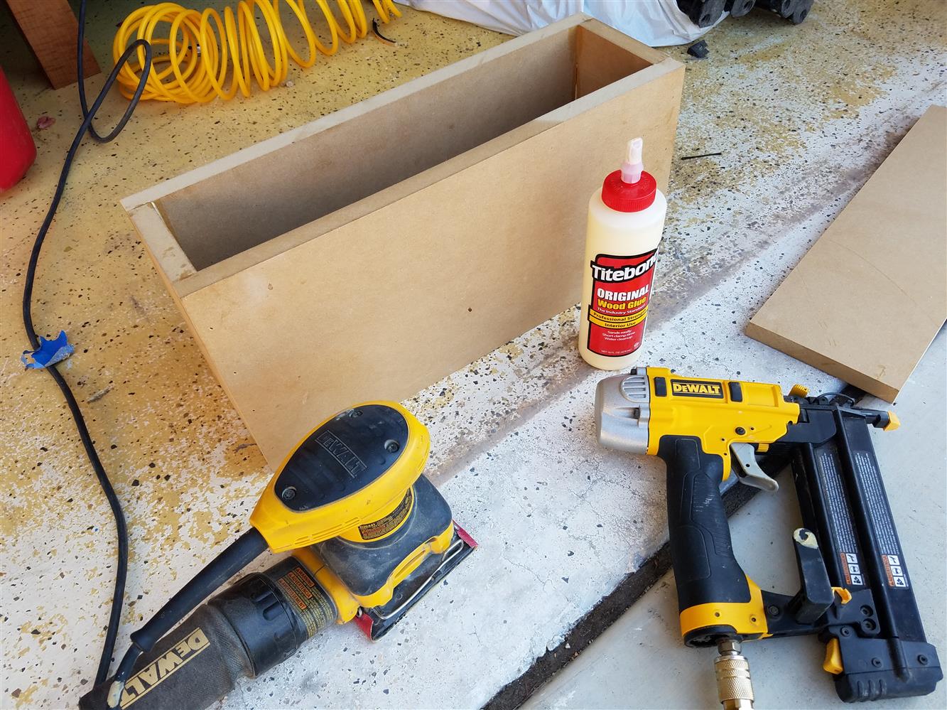
Build Pics
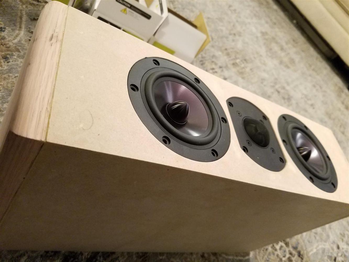


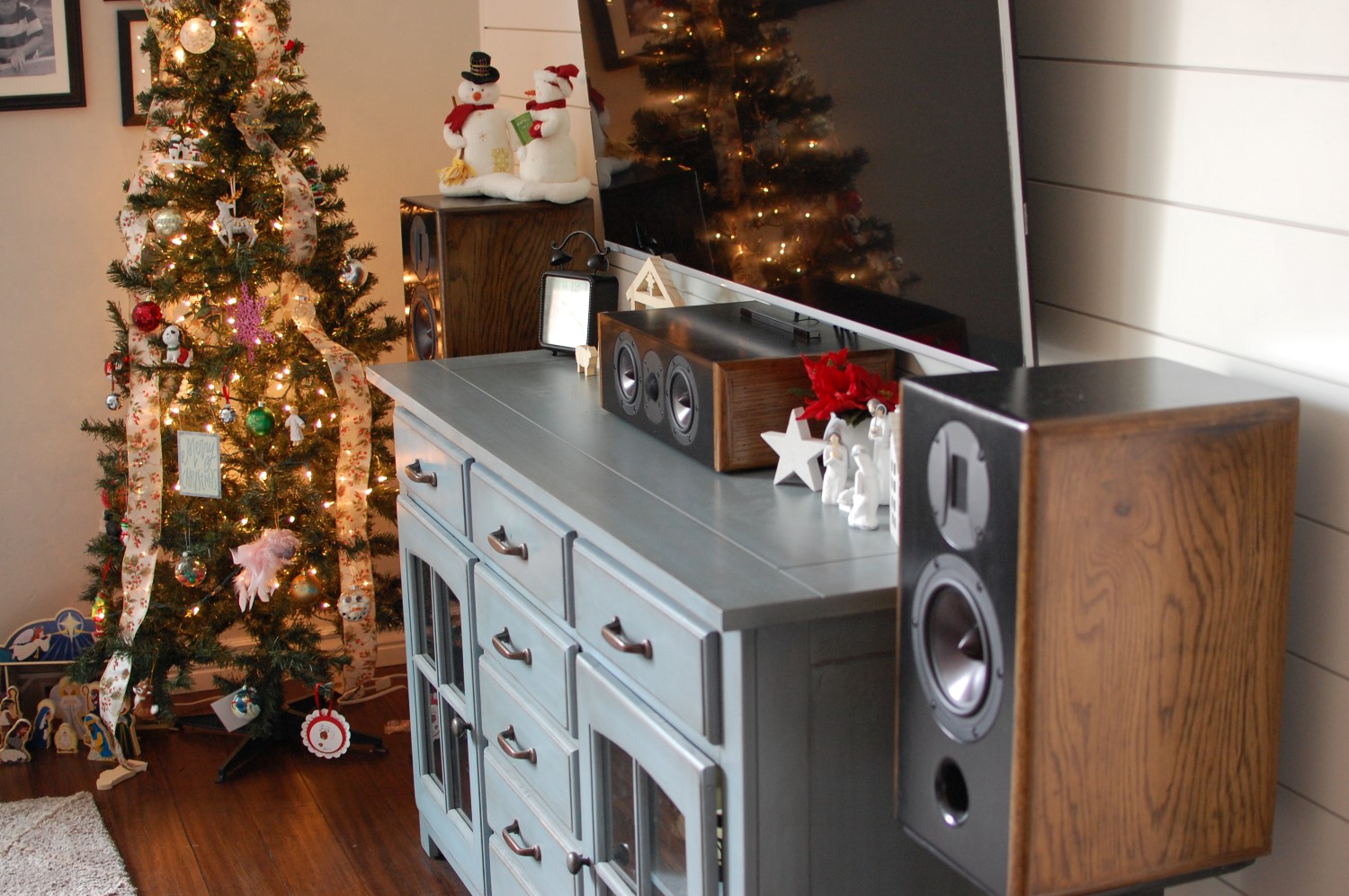
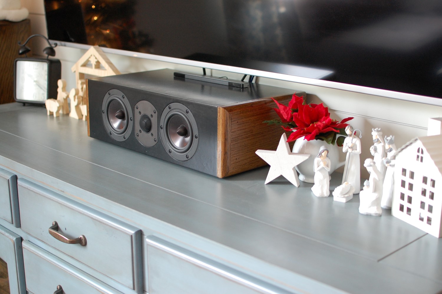
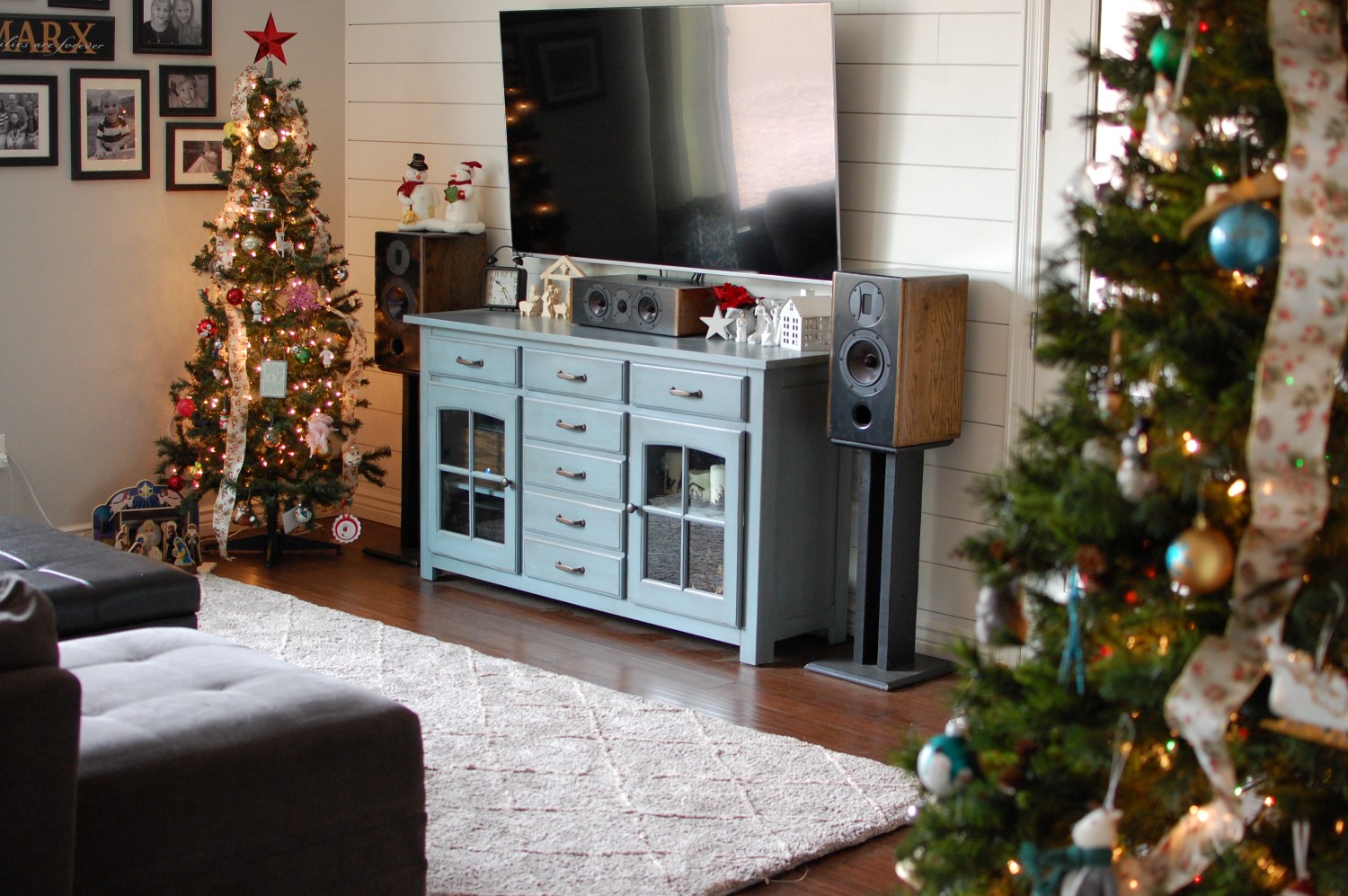
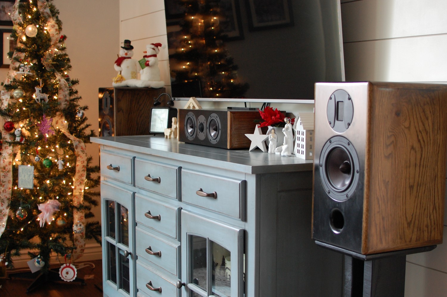
Complete Pics
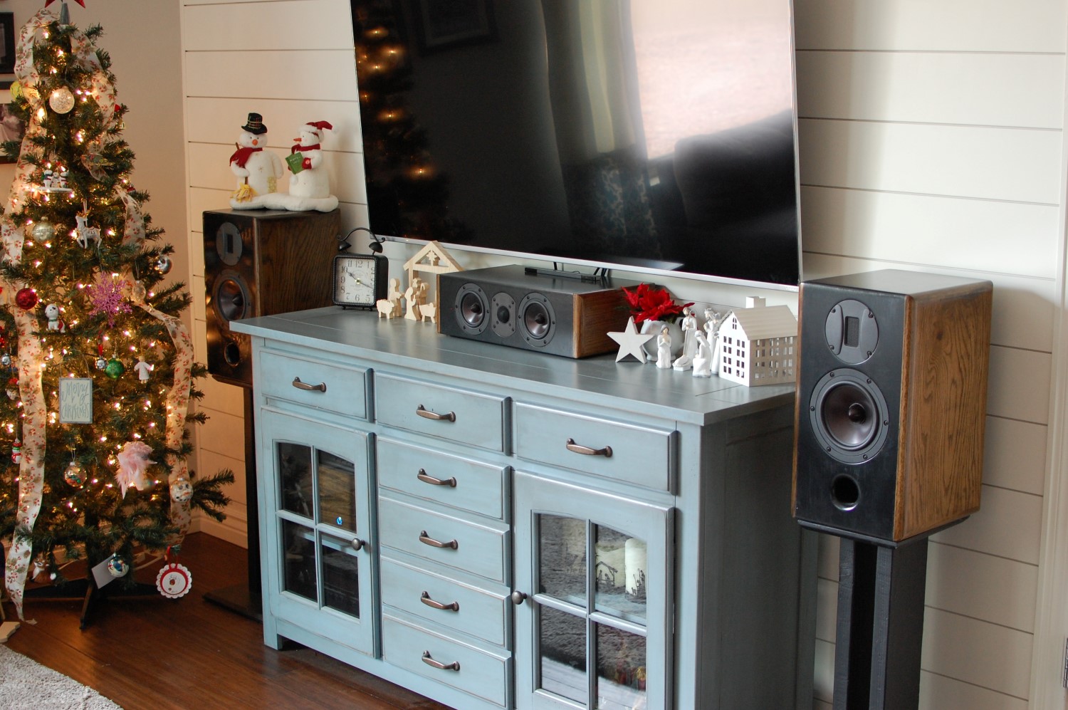
Christmas-Themed Pics
Enclosure Design, Simulations and Measurements

Looks great, thanks for sharing! Are yous till satisfied one year later?
I’m considering building one of these myself as a start of a new set. Would you have a more high res version of the CAD drawing available, the smaller font is not really readable.
Thanks! I can easily say a year later I have been very happy with this speaker. Despite the inherent design limitations as discussed, it still sounds great no matter where you are seated, dialogue is clear, it sounds well matched and balanced, every movie we have thrown at this has sounded fantastic. I’ve never thought, I should tweak this or changed that, it sounds spot-on for my tastes. I’ll upload a higher res version and email you one as well. I believe most of the dimensions are true to the final design, so you should be fairly safe with this.
What are you thinking of doing for your complete set? A pair of mains to match?
Dan
Thanks for your quick response, much appreciated! A set of matching mains will definitely follow indeed. I currently have a pair of mains that I build about 10 years ago as a bit of a test case for many abilities. Then became a dad and the real thing never followed ;-) Now looking to scale things up a bit. I’ve been looking at Paul Carmody’s designs as well but must admit I like the looks of this one best. Still trying to get my head around the details of. How to ensure the best match between speakers (I’m mostly about the DIY fun, not so well versed in audio technicalities).
Really nice looking speaker. Do you happen to have any plans for the 3 way speaker you mentioned above? I would like to build my own and am reading whatever I can to try and understand design, crossover etc. How do you go about designing a crossover? Once I have decent understanding of everything I’ll start ordering parts and start building, I figure a center is the best speaker to start with. ( I also want to build a folded horn subwoofer sooner than later).
Cheers!!
Hey Stu, thanks for the comment! I do not have any plans for the 3-way. I have just started looking at one, but so far it is only in the early design stages so I don’t really have anything I can share. I will say that I have been playing around with potential crossover options for a 3-way using Jeff Bagby’s PCD 8.0 and can recommend that route as a good place to start. Download the stock frd and zma files from PE’s website and start to get a feel for what adjustments can be made and what they do. In the end you will need to measure your speakers and use measured data to really get the crossover right, but in the meantime you can at least learn how to apply different filters and see what they do to the plots. Though if you’re just starting out, my recommendation is to model a simple two-way first. Just so you can learn how to use the spreadsheet. I’m not saying to just build a two-way, if you want to do a three-way then I’d say go for it, but the crossover will be more complex and harder to get right. So it’s easier to learn how to use PCD with a two-way first, and then move on to a three-way. And a center channel isn’t necessarily easier to design than a regular set of bookshelf speakers, it is only easier to build since you only have to build one! Good luck, let me know if you have any other questions.
Subject: How to Solve Center Channel Speaker Dilemma
I’m not a speaker DIYer but came upon this page while searching for help. With $1200.00 in Sony card points due to expire on December 31st, the horrible problem I will face if I choose a 65 over a 55″ Sony A95L TV is that because I want to watch it from 11 ft away and want my eyes to fall just below the center of the screen, the bottom of the TV will have to be only ~ 5″ above the floor-making it impossible to place any respectably sounding center speaker in between. And mounting the center speaker above the TV is not an option, nor do I want to have the main speakers much closer than 10 ft from me.
The only other option is to go with the 55″ and watch that from 11 ft way, a foot or so behind the speakers. And I can’t place the 55” TV past the front of the main speakers to be closer to me as that would most likely cause bad early reflections.
If only Revel, Legacy, Wharfdale or other turnkey HT speaker system brands made an excellent pair of vertical center speakers to be placed to the sides of the TV, and which would complement the directivity pattern of the main speakers.
Suggestions welcomed.
Hey Greg, thanks for the comment, and the interesting dilemma you present. So a couple of things, how low do you want to mount this TV? Having the bottom of the TV only 5″ above the floor seems unusual. You may be placing too much priority on wanting the center of the TV at or around eye level. Most people get away with placing the TV and a small entertainment console below it, along with a center channel, without any issues. The only thing small enough to fit in that location you describe would be a sound bar. And I’m guessing you’re not willing to compromise that much. So you’re on the search for a decent, low-profile center channel. I haven’t searched for one, but one thing I can offer is that perhaps you should reconsider your intent for mounting the TV so low. How badly do you want the TV at this particular height that you’re willing to give up on potentially a really good center channel to get there? What will bother you more in the end, crappy sound and poor center dialogue, or a TV that’s just a couple inches higher than you would have preferred? My TV arguably is too high, by most standards, that media console my wife fell in love with drove my TV height and while it’s not my favorite, it bothers me less than I thought it would. Also hence my reason for designing a good but small center channel. I think you might find it better to compromise on your TV height than the quality of the center channel you can fit underneath it. Just something to consider. I’d hunt down the center channel you really want, and then ask yourself if you can give up on the “optimum” TV height. Which can be pretty subjective. Also, don’t get the 55″. You will wish it were bigger eventually. I have a 65″ and while at first it seemed great, I’m already itching to go to 75″ or even 85″ inches now. It’s a battle, but at 11 feet, the bigger TV is going to be more immersive, even it ends up being a little higher than you’d like. Good luck!